A golden rule in analytical chemistry says:
“The two digits before the decimal point are determined by sampling; the digits after the decimal by the lab.”
This means the lab personnel can work at their best with the latest state-of-the-art methods and instrumentation; however, if the sample delivered is doubtful, as an outcome of the lab efforts the results can never be anything but doubtful as well.
Such untrustworthy results, which are at least frustrating for the laboratory personnel, can lead to a long chain of false deductions and conclusions.
In practice, engineering, procurement, and construction contractors and boiler manufacturers still too often specify outdated designs. Neither the new requirements of modern power plants nor the possibilities offered by state-of-the-art system designs are taken into consideration.
This article provides an overview of the available and required technology in power cycle sampling and sample conditioning systems (SWAS). This brochure does not and cannot replace any well-known and established standards, such as VGB-S-006-00-2012-09-EN, or others (e.g., IAPWS TGD, EPRI, etc.). Rather, the intent is to provide a brief introduction as an initial aid, highlighting several important topics.
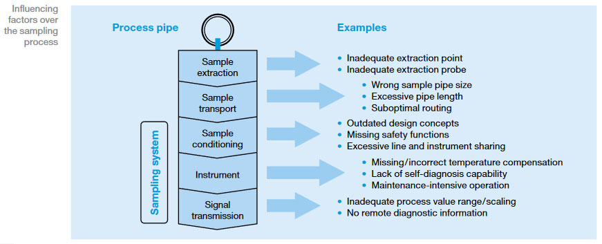
The sampling system is used to take samples from the water/steam circuit and auxiliary systems for continuously measuring operational values and undertake laboratory analysis. The analysis allows monitoring of the water and steam quality and control over chemical dosing.
Clearly, any sample taken must be representative, fully reflecting the composition and situation of the relevant process/system. Since those samples must be taken from high-pressure and high-temperature systems, certain conditioning, such as pressure reduction and cooling, is necessary before any monitoring or grab sampling can be performed. It must be kept in mind, that any conditioning will not alter or affect the composition of the sample.
It also needs to be emphasized that the risk of affecting any sample begins well before any conditioning – during sample extraction and routing. From experience, it can be said, that in numerous plants, extraction and routing is carried out inadequately, so any further measures down-stream are unhelpful, and all results obtained are at least doubtful and may be completely wrong.
Quote from VGB-S-010-T-00;2011-12.EN:
The medium that a sample is to be taken from can be either single-phase or dual-phase at the sampling point. Suspended solids (e.g., iron oxides) are not considered a separate phase. Thus, condensate with suspended solids may be considered a single-phase fluid, even if it contains two phases, which must be taken into consideration while sampling.
The following distinctions should be made:
All the recommended requirements are well described in the IAPWS technical guidance document, IAPWS TGD 6-13, the EPRI 2014 technical report “Guidance on Design, Operation, and Maintenance of Steam and Water Sample Conditioning Systems,” or the VGB standard, VGB-S-006-00-2012-09-EN.
The way the sample is extracted from the process plays a major role in whether or not the sample is representative and accurate. If certain requirements are not met, the sample may be completely incorrect and may deliver misleading results. This is especially true when taking samples from a dual-phase system, such as saturated steam, but it is also important when samples for determining total iron are taken from any system (e.g., condensate, feedwater, boiler water, etc.).
The installation of an appropriate sample probe is the key element here, followed by the proper adjustment of the flow conditions (keyword: isokinetic sampling!).
VGB-S-006-00-2012-09-EN and VGB-S-010-T00-2011-12.EN provide very important and useful suggestions as to exactly where the various samples should be extracted from in the different process lines.
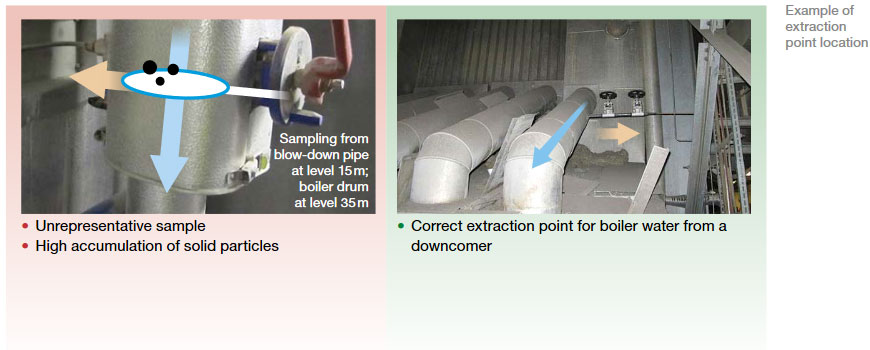
However, it needs to be emphasized here again that the generic selection of a process/system is not the only aspect that plays a significant role in obtaining correct and representative samples; the specific location within the individual process line must be taken into account, as well. A typical example is shown below.
The sampling probe may be installed in both vertical and horizontal process pipes, but when the extraction is taken from a horizontal line, possible deterioration of the sample composition must be considered. E.g. particles, such as corrosion products may accumulate in the lower part of the process pipe (6 o’clock position). In addition, those particles may not have fully reached the upper part of this pipe (12 o’clock position). Consequently, the 6 o’clock and 12 o’clock positions are clearly “no-go areas” and the 3 o’clock and 9 o’clock positions should be always used instead. More details can be found in Chapter 4.2 of VGB-S-006-00-2012-09-EN.
It is very important that the material of the sample pipe does not react with any components of the sample or alter the sample composition in any way. Therefore, high-alloy Ti-stabilized steels, such as 1.4571 (equivalent to AISI 316Ti) or 1.4404/1.4435 (equivalent to AISI 316L), should be used for all sample pipes. Low-alloy or unalloyed carbon steels should not be used under any circumstances.
A certain minimum flow velocity in the sample pipe is absolutely vital for various, important reasons, such as the following:
A widely accepted, not to mention recommended practice, is to adjust a sample flow to >30 l/h with a maximum of 60 l/h. By staying in the range of 30– 60 l/h and by using the recommended sample pipe sizes (see Table 1 below), all the requirements will be met. The upper limit of 60 l/h is due to the sample coolers’ capacity; it is also important not to exceed this limit, or the sample may become too hot.
Also, the routing of the sample pipes plays an important role. The basic rules can be seen here below.
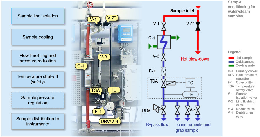
The function of the sample conditioning system is to ensure that samples are supplied to the instruments or for grab sampling at adequate pressure, flow, and temperature. In addition to the essential functional requirements, when designing a sample conditioning system, we must also consider the plant type and modes of operation from the perspective of safety requirements, operation and maintenance, and cost of ownership.
Once the sample reaches the sampling station, it must be properly and safely connected to the sample conditioning panel. In general, the following types of connections are recommended:
At the inlet of the sampling station, each line must be fitted with a shut-off valve upstream of the cooler, for maintenance and/or operational purposes. With a suitable sample isolation valve designed for the process pressure and temperature, double isolation valves are not required at the SWAS rack. If several sampling lines share a common sample cooler, backflow into the lower pressure sampling line(s) must be prevented by means of suitable shut-off valves.
In the cooling stage, samples are cooled from process temperatures to 3– 5°C above the temperature of the cooling water inlet. According to VGB-S006 (Sampling and Physico-Chemical Monitoring of Water and Steam Cycles), the sample temperature for correct sample temperature compensation should be in the range of 5– 45°C. Some propose secondary coolers to maintain a temperature very close to 25°C. It has to be noted that achieving exactly 25°C will never be possible and that large errors can be introduced into the measurements if unsuitable instruments with no temperature compensation are used. Modern instruments, like all Swan instruments, can handle a wide temperature range and will automatically compensate for changes.
According to VGB-S-006-00-2012-09-EN, secondary sample cooling – with a secondary cooler or a thermal bath which is fed through a closed, chilled water circuit – should ONLY be used if the primary cooling water is too warm to reduce sample temperatures below 45°C.
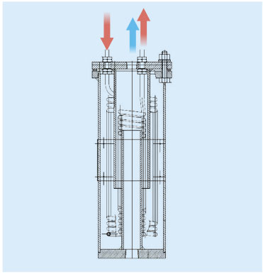
Cooling water (CW) quality is one of the most important aspects to be taken into consideration when designing a SWAS, as it is one of the main contributors to longer maintenance intervals. The use of non-demineralized water will always lead to clogging, scaling, and corrosion of coolers.
Remember: Samples from steam or boiler water and similar processes enter the cooler at very high temperatures (typically in a range of 150–600°C). Consequently, the surface of the cooling coils will be a similar temperature. If the cooling water contains dissolved minerals such as chloride, even high-alloy materials will be attacked and destroyed very quickly under these operating conditions. Also, there is no way to avoid these negative effects, if when such unsuitable water quality is used. Therefore, cooling should always be done with a closed cooling water system using demineralized water. For plants using other water qualities, it must be noted that frequent maintenance (e.g., acid cleaning) and component replacement may be necessary and that the sampling system may fail completely, thus resulting in complete loss of control over the plant’s chemistry.
To prevent risk of injury to personnel and damage to instrumentation, sampling conditioning systems must be equipped with a temperature shut-off valve cable to completely stop the hot sample. This can either be mechanical, with a fixed temperature switch-off point, or a pilotoperated valve, consisting of a temperature sensor, a temperature controller, and a pilot valve (pneumatic or solenoid).
The following measures must be met for proper and safe operation:
For pressure and flow regulation, the most suitable method, which is also recommended by the VGB and the ASME Performance Test Code (ASME PTC 19.11-2008), is the combination of a flow restriction valve upstream and a pressure-regulating element downstream. The back-pressure regulator will also provide a safe protection against excess pressure in the sampling system’s downstream shut-off valve.
As online instruments require a constant sample flow, this can only be ensured by controlling the sample inlet pressure at the instrument. In addition, every instrument must be equipped with a needle valve and a flow meter to set the sample flow at the recommended values. Rotameters installed at the sample distribution point are not appropriate for this important task. Flow should be measured at the end of the sample line and should be connected to a device that can out put an alarm. Swan instruments have an integrated flow measurement that is available as a signal output and an alarm relay. The alarm indication is always available, with or without signal output.
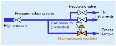
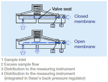
The back-pressure is regulated on the inlet side (Ports 1 and 3 in the next figure).
The operating principle is similar to that of an overflow valve. The pressure acts against a spring-loaded membrane; high pressure causes the valve to open wider to allow flow, thus reducing the pressure.
The division of the flow restriction and the pressure regulation follows the principle of separation of functions, for a simpler and safer system design.
With the back-pressure regulation, there are no small moving parts in the sample flow, minimizing maintenance costs!
The membrane-based Swan back-pressure regulators, with a low default pressure of 0.5 bar, have a large valve cross-section, allowing particles to flow through in the sample flow.
Back-pressure regulators provide reliable protection against high pressure: they open further when pressure increases.
By design, back-pressure regulators are thus safer against high-pressure events and less prone to particle clogging and while providing a more stable sample flow than forward-pressure regulators.
Sample Filtration (Dos and Don’t s)
When designing and drawing up specifications for a SWAS, always keep in mind that samples for determining total iron content must be taken regularly in every plant, as this is the only parameter that provides reliable feedback on whether the applied water chemistry are functioning as desired.
Because the overwhelming majority of total iron found in steam/water cycles consists of undissolved particles, special care must be taken to ensure that those particles are not removed during sampling, or erroneous results will be obtained, which might indicate optimal chemical conditions.
Sample filtration is always a controversial subject of discussion. The advantage of protecting valves and measuring equipment must be weighed against the disadvantage of additional maintenance and potential sample bias.
If required, an additional fine filter can be connected upstream of individual particle-sensitive instruments, and precautions can be taken to ensure that an unadulterated grab sample can be taken upstream of the filter.
Quote from IAPWS TGD6-13 (2014): “Any sample line filters should be removed or bypassed prior to sampling for corrosion products.”
During any start-up operation, a higher concentration of particles or corrosion products may be expected. This is caused by fast-changing conditions (temperature, pressure, flow) in the various systems. This is especially true in cycling plants with frequent start-stop operations. Those particles will quickly and easily block the sampling lines, causing all the measurements to be interrupted and thereby hampering chemical control of the unit during this critical operating phase.
For this reason, flushing equipment for the sampling line is:
The flushing line must branch off upstream of the sample cooler to prevent contamination and clogging of the pressure control valves and thermal overload of the sample cooler caused by the high sample flow rate.
The blow-down valves drain into a common closed header (hot blow-down header) routed to a safe drain capable of handling high temperatures.
As explained in many documents and standards, the measurement of conductivity downstream of a strong acidic cation exchanger is always a key parameter to be measured. The cation exchange process upstream of the conductivity measuring cell must therefore work properly and adequately. On the one hand, all cations must be exchanged against H+ ions and no ion slippage should take place; on the other hand, the sample’s travel time through the cation exchanger should be as short as possible to minimize measuring delays.
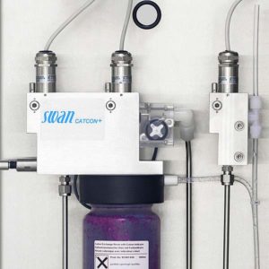
This requirement can be perfectly fulfilled by using the latest state-of-the-art technology, such as EDI-based cation exchange.
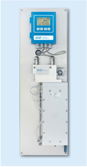
AMI CACE Conductivity Monitor with Automatic Resin Regeneration
Such a device always provides uninterrupted and complete cation exchange, while utilizing a very small volume, so the sample delay is minimal. Another major advantage is that regular and frequent resin replacement or regeneration is unnecessary, meaning that there are no more monitoring interruptions and there is no more need to handle dangerous liquids, such as acids for regeneration; what’s more, the maintenance effort is greatly reduced.
In cases where a classic cation exchanger cartridge is preferred, there are a few key and essential requirements:
Far more details are provided and explained in the article published in the PPCHEM Journal, issue no. 2006 8 (11): H. Maurer, Cation Conductivity: Facts and Fiction.
AMI Deltacon Online Conductivity Analyzer with Degasser Reboiler
For each instrument, a dedicated pipe branch supplies samples from upstream of the back-pressure regulator to the instrument inlet.
The individual lines must branch off as close as possible to the back-pressure regulator in order, to maintain the sample flow and pressure at the instrument inlet. The tubes should be sized to ensure a proper sample flow speed (i.e., 4–5mm inner diameter).
If the instrument itseld is not fitted with one, a needle valve is required to regulate the flow to the individual instrument. The same valve will allow the instrument to be isolated for maintenance purposes.
The SWAS subsystem is delivered as prefabricated, factory-assembled module with all internal hydraulic and electric connections. Common headers shall be planned for cooling water supply, cooling water return, cold drain, and sample line hot blow-down.
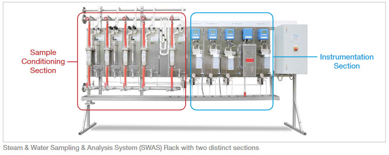
The SWAS has two distinct sections:
In both sections, all components should be grouped and arranged by sample line in a modular and readable manner, allowing easy operation and access to all components for maintenance. A modular design also allows simple replacements or upgrades during operation. It is recommended to plan for at least 10% to 20% extra spare to accommodate for future extensions/modifications.
Furthermore, on the instrumentation side, all elements of each measurement chain (i.e., the sensor, flow cell, and relevant transmitter) should be grouped in a clear and ergonomic manner (i.e. transmitter at eye level and all other components related to the measurement chain within reach of the operator when standing in front of the transmitter).
A local electrical cabinet provides power distribution to all components of the SWAS and signal interface to the customer’s control system (terminal strip for analog/binary signals or fieldbus interface).
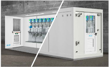
The shelter houses and protects the sampling and analyzing equipment and provides a suitable and safe work environment for the chemistry operators/lab technicians. The shelter structure is typically a self-contained painted, galvanized steel structure for installation on a flat concrete foundation (strip or slab foundation). The shelter’s roof, walls, and floor provide a full enclosure and protect the equipment.
The shelter should be designed for outdoor installation in the given environmental conditions. Insulation and air conditioning are provided to maintain indoor temperature conditions of 25+/-8°C under all outside atmospheric conditions and factoring in internal heat sources. In case of sub-zero outdoor temperatures, the shelter should be equipped with enough heating capacity to prevent any freezing of the equipment even if there is no heat input from sample lines. In a wet/humid environment, wood/plywood/ rockwool or any other water absorbent material should not be used.
The shelter access door is provided with an emergency exit function. Shelters longer than 6 m require two access doors.
A rack-based installation is the most common and cost-effective solution for indoor installations. All components of the system are mounted on panels on the sides of the rack. The cooling water headers and hot blow-down collector are installed on supports on the rack’s structure. The rack can be completely pre-assembled and factory tested, which allows very fast installation on-site.
The rack structure must be properly designed to provide sufficient stability for transport and installation on-site. A welded, unpainted stainless steel (1.4301) structure is recommended to withstand harsh site conditions. The piping and mounting plates for coolers and instruments are also made of stainless steel. It should be noted that a mix of different materials can lead to an increased risk of corrosion.
There are different design concepts that can be pursued depending on the available space and installation location.
A single-sided rack design offers the advantage of having components (coolers, instruments, and the electrical cabinet) facing the operator. This clearly associates the sampling and analysis equipment with the respective measuring point, which makes the system very simple to operate and maintain. The rack can be installed directly next to a wall, or at any location where access from only one side is available.
A free-standing rack with supports for floor mounting is the standard solution for simple transport and installation. There are also wall-mounted frames, which might be split into different sections. Such a design can be used when the sampling system is installed in a narrow room, to give the operator sufficient space. However, it requires additional efforts for installation (lifting, alignment etc.) and a proper support structure to sustain the weight of the system.
Optionally, the rack can be equipped with a protective roof, lights, leveling elements, or mounting plates for other equipment such as pumps, a drain collector tank, chiller, or chiller bath.
Double-sided sampling rack
By installing components on both sides of the rack (typically, sample conditioning on one side and analyzers on the other), less installation space is required. A double-sided rack is also a suitable solution to accommodate larger systems. It must be ensured that the operator can access both sides of the rack for operation and maintenance.
A cabinet can accommodate smaller sampling systems and is mainly used to provide suitable ambient protection when the sampling system is installed outdoors, close to the sampling take-off point. A cabinet can also be used when there is risk of contamination from a very dusty environment or spillage.
Different materials are available for cabinets, including aluminum, painted/galvanized steel, and fiberglass-reinforced plastic. In outdoor installations, sandwich panels are used for better thermal insulation and heaters can be applied for freeze protection. The cabinet is ventilated to evacuate heat from hot samples and instruments. For high ambient temperatures, an AC unit can be installed.
In recent years, with the increase of power plants operating in cycling mode and frequent start stop operations, special automatization features are sometimes requested for the design of sample conditioning and analysis systems. Because some sample conditioning components and analyzers need regular maintenance, complete automation is not possible.
The following chapters contain some recommendations related to these special features which can help prevent highly complex and costly sample conditioning system designs.
Requirements for the complete automation of the sample valves upstream of the sample coolers would make systems very costly and yet offer very limited operational benefits.
The sample shut-off and blow-down valves are designed with a minimum valve cross-section, a special seat, and flow geometry to prevent and minimize clogging caused corrosive particles in the sample and are rated to withstand full process pressure and temperature.
A special pneumatic actuator is necessary if these valves are designed for automatic operation from the main control system. For samples with medium (=300°C) and high (600°C) temperatures, these pneumatically actuated valves need to have an airor water-cooled spindle extension.
Valves like these are not available off-the-shelf and supply and installation costs are quite high.
Typically, sample line flushing is necessary during start-up operations (initial start-up or after extended standstills). More frequent line flushing may be necessary for plants with corrosion issues and a higher content of corrosice particles.
However, frequent sample line flushing does not mean that automatic flushing valves are required. It is a simple operation that lasts only a few minutes and can easily be performed manually.
Sometimes, two sample lines share one sample conditioning panel, for example, where the super-heated steam samples are monitored continuously, and saturated steam samples are monitored regularly for diagnosis or troubleshooting purposes. The chemist or operator decides when to switch the sample line from superheated to saturated steam.
Designing pneumatic valves upstream of the sample cooler for automatic switching significantly increases the cost of the sample conditioning panel and offers no operational benefits, since manual valve switching is a process that lasts only a few minutes.
For fast-start and frequently-started combined cycle plants, the IAPWS states that it is beneficial to keep the key instruments on a continuously refreshing cycle with demineralized water during shutdown or offline periods in order to maintain analyzer operation. The highest priorities are detecting condenser leaks and ensuring steam purity for the turbine admission during startup.
However, it should be noted that automatically flushing with water has some consequences for the critical analyzers: higher consumption of demineralized water is required to keep the analyzer operational while the plant is stopped (an average of 10 l/h per analyzer), the sensitivity of sodium sensors may be reduced if they are continuously flushed with high-purity water, and consumption may be higher for analyzer reagents and other consumables.
Cooling Water: Main Cooling System
In the main cooling water circuit, water quality monitoring is also critical for achieving suitable chemical conditions in the circuit and for automatically controlling of the chemical dosing system. Sample extraction and conditioning are different than other parts of the water steam cycle, but no easier or less important. Since they have different natures and boundary conditions, the sampling systems for the main cooling water and those for the water steam cycle should always be defined.
The sample extraction site must be designed after evaluating the cooling water circuit in each individual power plant to ensure that the sample is always representative of what is happening in the process and that the time lag is minimized as much as possible.
Wherever possible, it is advisable to extract the sample from sites within the circuit where cooling water is continuously flowing. If inline sensors are located in large basins where the water is stagnant, the measurements will not be representative.
Sample are typically extracted from large, open channels or large pipes, running the risk that the sample pressure is insufficient to provide the necessary sample flow and velocity to the analyzers.
It is important to extract the sample on the pressure side of the circuit, to limit the need for a sample pump, cut operating costs, and increase reliability. A sample extraction pump should be used only when there is no other alternative. Sample extraction pumps have a small cross-section because the required sample flow for analyzers is typically below 60 l/h and they are prone to failure (small sump pumps in pits are prone to clogging by particles; suction pumps typically lose suction height due to wear).
Water from the main cooling circuit will have high contents of salts, suspended solids, and organics compound. Therefore, it is important to locate the extraction point in the piping as recommended in Chapter 3.1 to minimize disturbances (suspended solids, gas bubbles, or foam).
It is highly advisable to design a sample line flushing valve at the sampling panel inlet in order to eliminate any suspended solids that have accumulated in the transport line.
If necessary, use fast loop cycling to avoid sedimentation in the sample transport line:  Additionally, depending on the required measurements and analyzers for the main cooling circuit, sample filtration upstream of the analyzers may be also necessary. Some analyzers have an optional automatic cleaning module to reduce maintenance caused by biological activity.
For measurements such as residual biocide concentration, it is critical that the analyzer is located as close as possible to the process in order to reduce the length of the sample transport line. Therefore, the sampling system for the main cooling water should be designed as a separat subsystem from the main water steam cycle sampling system.
In a power plant’s effluent or wastewater discharge system, it is also mandatory to continuously monitor the water quality parameters to ensure that they comply with local environmental legislation.
The recommendations for locating sample extraction, sample conditioning, and effluent sampling systems are similar to those indicated for the main cooling system in Chapter 8
As per VGB, IAPWS, and EPRI recommendations, the sampling site for condensate is the main condensate downstream of the condensate extraction pumps. Using the main condensate sample for permanent monitoring has the following advantages:
The online analyzers in the main condensate sample indicate condenser leaks early on; the following sampling options are available when attempting to identify the leaking tube sheet:
VGB-S-006-00-2012-0F9-EN recommends that multiple tapping points be installed below the condensate level at various critical locations in the individual condensers and condensate pipes. Grab samples can be extracted at various points and analyzed in the laboratory using a portable membrane pump. Along with comprehensive online monitoring in the main condensate, this setup provides great flexibility and efficient locating of leaks at a reasonable cost.
The affected condenser can be identified quickly from each condenser’s condensate pipe sample. A leak’s probable location within the condenser can be estimated by comparing grab samples taken from different tapping points.
Sometimes, technical specifications from technical consultants and the owners’ engineers will list a condenser hotwell sample and associated online measurements by default. If such requirements are included in an EPC contract, this could cause technical discussions.
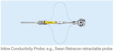
A common compromise between the EPC and the operator to provide some form of hotwell condensate monitoring is specific conductivity probes, installed directly in the condenser walls at various locations. The probe closest to the leak should indicate the highest conductivity values.
The most expensive and complex sampling setup is a dedicated sampling and instrumentation skid for hotwell condensate. This is technically feasible, but it is complex and quite costly.
Therefore, the need and expected benefit of such a system should be carefully examined and compared with the alternatives listed above. The recommendation is to design such skids only for very large condensers that can be partially isolated on the cooling water side during operation.
Detailed design considerations for this hotwell sampling skid are included in a technical note published by Manuel Sigrist and entitled: “TechNote_Condenser Monitoring_Rev1 3”
Why is it important for an online analyzer to have integrated self-diagnostic capabilities? This way, measured values can be validated, and instruments which provide diagnosis values and alarms can be monitored.
All Swan analytical instruments feature integrated wide-range temperature compensation of their measurements to the reference temperature of
25°C.
Sample temperatures between 5–45°C can be handled by all Swan instruments without measurement bias. Unlike many instruments that require precise thermostatic control of the sample temperature at 25°C, Swan instruments can compensate for the effect of sample temperatures between 5–45°C.
As explained in Chapter 5.3, this limits the need for secondary cooling. Even with a secondary cooling stage, measurements will not be dependent on the chillers’ ability to maintain constant sample temperatures.
For comparison and reference measurements, it is essential to ensure that the handheld and laboratory measuring devices have the same equipment and functionality as the online devices in order to obtain representative and reproducible measurement results. Otherwise, the discrepancies in measurements will lead to increased effort and run the risk that the water and steam chemistry quality status will be assessed incorrectly.
As per VGB-S006-2012, Chapter 5.2 on quality assurance, the quality of continuous online instruments may be ensured by the following technical measures:
1) Proper design of the sampling system and sample conditioning
2) Automatic diagnostic functions being integrated in the instruments, such as:
Typically, modern instruments offer several possibilities for signal exchange, either traditional hardwired analog signals or more modern digital communication (e.g., HART, Bus, etc.)
Power plants today are widely operated in a cycling mode and have fewer operators on duty; therefore, it is essential to have a high thrust in the indicated values in the main control room.
However, this cannot be achieved with analog signals above.
A SWAS with 10 lines, 20 instruments, and a few auxiliaries will typically have around 50–70 signals exchanges with the DCS, which is more than most auxiliaries in a power plant.
When it comes to signal exchange between the SWAS and the DCS, hardwired signal exchange is still required in many power plants.
The alternative is to use digital bus-based communication for signal exchange between the SWAS and the users of SWAS data (the DCS, instrumentation and control (I&C), or chemical department). State-of-the-art instruments offer bus communication options (e.g., Profibus/Modbus).
Modern instruments also offer a digital HART communication option. HART will allow the transmission of more information from the instruments: sample flow, cation resin consumption, reagent levels, error messages, etc.
Swan instruments have optional communication interfaces available for Profibus DP, Modbus RTU, and HART Protocol Revision 7.5.
As described in Chapter 9.2, modern online instruments feature self-diagnostic capabilities to validate the measured values, to monitor instrument status, and to provide diagnostic values and alarms.
If diagnostic information is available, not only in the instrument itself but also remotely, reliable and validated measurements and alarms will be possible in main control system (DCS). This will also increase the trust that operators working in the main control room have in the online analyzers.
In many parts of the world, it is still commonpractice to specify a SWAS design consisting of what is known as a wet rack and a dry rack.
The wet rack contains the sample conditioning equipment and a grab sampling sink, as well as flow cells and sensors. The dry rack is reserved for transmitter electronics (usually panel-mounted transmitters).
These designs date from a time when transmitters did not have the necessary electrical protection (IP66). State-of-the-art instruments are now designed based on functional arrangements, as recommended by VGB-S006-2012.


A golden rule in analytical chemistry says:
“The two digits before the decimal point are determined by sampling; the digits after the decimal by the lab.”
This means the lab personnel can work at their best with the latest state-of-the-art methods and instrumentation; however, if the sample delivered is doubtful, as an outcome of the lab efforts the results can never be anything but doubtful as well.
Such untrustworthy results, which are at least frustrating for the laboratory personnel, can lead to a long chain of false deductions and conclusions.
In practice, engineering, procurement, and construction contractors and boiler manufacturers still too often specify outdated designs. Neither the new requirements of modern power plants nor the possibilities offered by state-of-the-art system designs are taken into consideration.
This article provides an overview of the available and required technology in power cycle sampling and sample conditioning systems (SWAS). This brochure does not and cannot replace any well-known and established standards, such as VGB-S-006-00-2012-09-EN, or others (e.g., IAPWS TGD, EPRI, etc.). Rather, the intent is to provide a brief introduction as an initial aid, highlighting several important topics.
The sampling system is used to take samples from the water/steam circuit and auxiliary systems for continuously measuring operational values and undertake laboratory analysis. The analysis allows monitoring of the water and steam quality and control over chemical dosing.
Clearly, any sample taken must be representative, fully reflecting the composition and situation of the relevant process/system. Since those samples must be taken from high-pressure and high-temperature systems, certain conditioning, such as pressure reduction and cooling, is necessary before any monitoring or grab sampling can be performed. It must be kept in mind, that any conditioning will not alter or affect the composition of the sample.
It also needs to be emphasized that the risk of affecting any sample begins well before any conditioning – during sample extraction and routing. From experience, it can be said, that in numerous plants, extraction and routing is carried out inadequately, so any further measures down-stream are unhelpful, and all results obtained are at least doubtful and may be completely wrong.
Quote from VGB-S-010-T-00;2011-12.EN:
The medium that a sample is to be taken from can be either single-phase or dual-phase at the sampling point. Suspended solids (e.g., iron oxides) are not considered a separate phase. Thus, condensate with suspended solids may be considered a single-phase fluid, even if it contains two phases, which must be taken into consideration while sampling.
The following distinctions should be made:
All the recommended requirements are well described in the IAPWS technical guidance document, IAPWS TGD 6-13, the EPRI 2014 technical report “Guidance on Design, Operation, and Maintenance of Steam and Water Sample Conditioning Systems,” or the VGB standard, VGB-S-006-00-2012-09-EN.
The way the sample is extracted from the process plays a major role in whether or not the sample is representative and accurate. If certain requirements are not met, the sample may be completely incorrect and may deliver misleading results. This is especially true when taking samples from a dual-phase system, such as saturated steam, but it is also important when samples for determining total iron are taken from any system (e.g., condensate, feedwater, boiler water, etc.).
The installation of an appropriate sample probe is the key element here, followed by the proper adjustment of the flow conditions (keyword: isokinetic sampling!).
VGB-S-006-00-2012-09-EN and VGB-S-010-T00-2011-12.EN provide very important and useful suggestions as to exactly where the various samples should be extracted from in the different process lines.
However, it needs to be emphasized here again that the generic selection of a process/system is not the only aspect that plays a significant role in obtaining correct and representative samples; the specific location within the individual process line must be taken into account, as well. A typical example is shown below.
The sampling probe may be installed in both vertical and horizontal process pipes, but when the extraction is taken from a horizontal line, possible deterioration of the sample composition must be considered. E.g. particles, such as corrosion products may accumulate in the lower part of the process pipe (6 o’clock position). In addition, those particles may not have fully reached the upper part of this pipe (12 o’clock position). Consequently, the 6 o’clock and 12 o’clock positions are clearly “no-go areas” and the 3 o’clock and 9 o’clock positions should be always used instead. More details can be found in Chapter 4.2 of VGB-S-006-00-2012-09-EN.
It is very important that the material of the sample pipe does not react with any components of the sample or alter the sample composition in any way. Therefore, high-alloy Ti-stabilized steels, such as 1.4571 (equivalent to AISI 316Ti) or 1.4404/1.4435 (equivalent to AISI 316L), should be used for all sample pipes. Low-alloy or unalloyed carbon steels should not be used under any circumstances.
A certain minimum flow velocity in the sample pipe is absolutely vital for various, important reasons, such as the following:
A widely accepted, not to mention recommended practice, is to adjust a sample flow to >30 l/h with a maximum of 60 l/h. By staying in the range of 30– 60 l/h and by using the recommended sample pipe sizes (see Table 1 below), all the requirements will be met. The upper limit of 60 l/h is due to the sample coolers’ capacity; it is also important not to exceed this limit, or the sample may become too hot.
Also, the routing of the sample pipes plays an important role. The basic rules can be seen here below.
The function of the sample conditioning system is to ensure that samples are supplied to the instruments or for grab sampling at adequate pressure, flow, and temperature. In addition to the essential functional requirements, when designing a sample conditioning system, we must also consider the plant type and modes of operation from the perspective of safety requirements, operation and maintenance, and cost of ownership.
Once the sample reaches the sampling station, it must be properly and safely connected to the sample conditioning panel. In general, the following types of connections are recommended:
At the inlet of the sampling station, each line must be fitted with a shut-off valve upstream of the cooler, for maintenance and/or operational purposes. With a suitable sample isolation valve designed for the process pressure and temperature, double isolation valves are not required at the SWAS rack. If several sampling lines share a common sample cooler, backflow into the lower pressure sampling line(s) must be prevented by means of suitable shut-off valves.
In the cooling stage, samples are cooled from process temperatures to 3– 5°C above the temperature of the cooling water inlet. According to VGB-S006 (Sampling and Physico-Chemical Monitoring of Water and Steam Cycles), the sample temperature for correct sample temperature compensation should be in the range of 5– 45°C. Some propose secondary coolers to maintain a temperature very close to 25°C. It has to be noted that achieving exactly 25°C will never be possible and that large errors can be introduced into the measurements if unsuitable instruments with no temperature compensation are used. Modern instruments, like all Swan instruments, can handle a wide temperature range and will automatically compensate for changes.
According to VGB-S-006-00-2012-09-EN, secondary sample cooling – with a secondary cooler or a thermal bath which is fed through a closed, chilled water circuit – should ONLY be used if the primary cooling water is too warm to reduce sample temperatures below 45°C.
Cooling water (CW) quality is one of the most important aspects to be taken into consideration when designing a SWAS, as it is one of the main contributors to longer maintenance intervals. The use of non-demineralized water will always lead to clogging, scaling, and corrosion of coolers.
Remember: Samples from steam or boiler water and similar processes enter the cooler at very high temperatures (typically in a range of 150–600°C). Consequently, the surface of the cooling coils will be a similar temperature. If the cooling water contains dissolved minerals such as chloride, even high-alloy materials will be attacked and destroyed very quickly under these operating conditions. Also, there is no way to avoid these negative effects, if when such unsuitable water quality is used. Therefore, cooling should always be done with a closed cooling water system using demineralized water. For plants using other water qualities, it must be noted that frequent maintenance (e.g., acid cleaning) and component replacement may be necessary and that the sampling system may fail completely, thus resulting in complete loss of control over the plant’s chemistry.
To prevent risk of injury to personnel and damage to instrumentation, sampling conditioning systems must be equipped with a temperature shut-off valve cable to completely stop the hot sample. This can either be mechanical, with a fixed temperature switch-off point, or a pilotoperated valve, consisting of a temperature sensor, a temperature controller, and a pilot valve (pneumatic or solenoid).
The following measures must be met for proper and safe operation:
For pressure and flow regulation, the most suitable method, which is also recommended by the VGB and the ASME Performance Test Code (ASME PTC 19.11-2008), is the combination of a flow restriction valve upstream and a pressure-regulating element downstream. The back-pressure regulator will also provide a safe protection against excess pressure in the sampling system’s downstream shut-off valve.
As online instruments require a constant sample flow, this can only be ensured by controlling the sample inlet pressure at the instrument. In addition, every instrument must be equipped with a needle valve and a flow meter to set the sample flow at the recommended values. Rotameters installed at the sample distribution point are not appropriate for this important task. Flow should be measured at the end of the sample line and should be connected to a device that can out put an alarm. Swan instruments have an integrated flow measurement that is available as a signal output and an alarm relay. The alarm indication is always available, with or without signal output.
The back-pressure is regulated on the inlet side (Ports 1 and 3 in the next figure).
The operating principle is similar to that of an overflow valve. The pressure acts against a spring-loaded membrane; high pressure causes the valve to open wider to allow flow, thus reducing the pressure.
The division of the flow restriction and the pressure regulation follows the principle of separation of functions, for a simpler and safer system design.
With the back-pressure regulation, there are no small moving parts in the sample flow, minimizing maintenance costs!
The membrane-based Swan back-pressure regulators, with a low default pressure of 0.5 bar, have a large valve cross-section, allowing particles to flow through in the sample flow.
Back-pressure regulators provide reliable protection against high pressure: they open further when pressure increases.
By design, back-pressure regulators are thus safer against high-pressure events and less prone to particle clogging and while providing a more stable sample flow than forward-pressure regulators.
Sample Filtration (Dos and Don’t s)
When designing and drawing up specifications for a SWAS, always keep in mind that samples for determining total iron content must be taken regularly in every plant, as this is the only parameter that provides reliable feedback on whether the applied water chemistry are functioning as desired.
Because the overwhelming majority of total iron found in steam/water cycles consists of undissolved particles, special care must be taken to ensure that those particles are not removed during sampling, or erroneous results will be obtained, which might indicate optimal chemical conditions.
Sample filtration is always a controversial subject of discussion. The advantage of protecting valves and measuring equipment must be weighed against the disadvantage of additional maintenance and potential sample bias.
If required, an additional fine filter can be connected upstream of individual particle-sensitive instruments, and precautions can be taken to ensure that an unadulterated grab sample can be taken upstream of the filter.
Quote from IAPWS TGD6-13 (2014): “Any sample line filters should be removed or bypassed prior to sampling for corrosion products.”
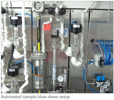
During any start-up operation, a higher concentration of particles or corrosion products may be expected. This is caused by fast-changing conditions (temperature, pressure, flow) in the various systems. This is especially true in cycling plants with frequent start-stop operations. Those particles will quickly and easily block the sampling lines, causing all the measurements to be interrupted and thereby hampering chemical control of the unit during this critical operating phase.
For this reason, flushing equipment for the sampling line is:
The flushing line must branch off upstream of the sample cooler to prevent contamination and clogging of the pressure control valves and thermal overload of the sample cooler caused by the high sample flow rate.
The blow-down valves drain into a common closed header (hot blow-down header) routed to a safe drain capable of handling high temperatures.
As explained in many documents and standards, the measurement of conductivity downstream of a strong acidic cation exchanger is always a key parameter to be measured. The cation exchange process upstream of the conductivity measuring cell must therefore work properly and adequately. On the one hand, all cations must be exchanged against H+ ions and no ion slippage should take place; on the other hand, the sample’s travel time through the cation exchanger should be as short as possible to minimize measuring delays.
This requirement can be perfectly fulfilled by using the latest state-of-the-art technology, such as EDI-based cation exchange.
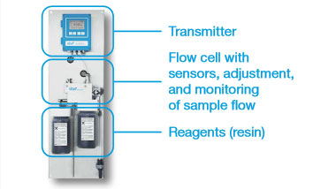
AMI CACE Conductivity Monitor with Automatic Resin Regeneration
Such a device always provides uninterrupted and complete cation exchange, while utilizing a very small volume, so the sample delay is minimal. Another major advantage is that regular and frequent resin replacement or regeneration is unnecessary, meaning that there are no more monitoring interruptions and there is no more need to handle dangerous liquids, such as acids for regeneration; what’s more, the maintenance effort is greatly reduced.
In cases where a classic cation exchanger cartridge is preferred, there are a few key and essential requirements:
Far more details are provided and explained in the article published in the PPCHEM Journal, issue no. 2006 8 (11): H. Maurer, Cation Conductivity: Facts and Fiction.
AMI Deltacon Online Conductivity Analyzer with Degasser Reboiler
For each instrument, a dedicated pipe branch supplies samples from upstream of the back-pressure regulator to the instrument inlet.
The individual lines must branch off as close as possible to the back-pressure regulator in order, to maintain the sample flow and pressure at the instrument inlet. The tubes should be sized to ensure a proper sample flow speed (i.e., 4–5mm inner diameter).
If the instrument itseld is not fitted with one, a needle valve is required to regulate the flow to the individual instrument. The same valve will allow the instrument to be isolated for maintenance purposes.
The SWAS subsystem is delivered as prefabricated, factory-assembled module with all internal hydraulic and electric connections. Common headers shall be planned for cooling water supply, cooling water return, cold drain, and sample line hot blow-down.
The SWAS has two distinct sections:
In both sections, all components should be grouped and arranged by sample line in a modular and readable manner, allowing easy operation and access to all components for maintenance. A modular design also allows simple replacements or upgrades during operation. It is recommended to plan for at least 10% to 20% extra spare to accommodate for future extensions/modifications.
Furthermore, on the instrumentation side, all elements of each measurement chain (i.e., the sensor, flow cell, and relevant transmitter) should be grouped in a clear and ergonomic manner (i.e. transmitter at eye level and all other components related to the measurement chain within reach of the operator when standing in front of the transmitter).
A local electrical cabinet provides power distribution to all components of the SWAS and signal interface to the customer’s control system (terminal strip for analog/binary signals or fieldbus interface).
The shelter houses and protects the sampling and analyzing equipment and provides a suitable and safe work environment for the chemistry operators/lab technicians. The shelter structure is typically a self-contained painted, galvanized steel structure for installation on a flat concrete foundation (strip or slab foundation). The shelter’s roof, walls, and floor provide a full enclosure and protect the equipment.
The shelter should be designed for outdoor installation in the given environmental conditions. Insulation and air conditioning are provided to maintain indoor temperature conditions of 25+/-8°C under all outside atmospheric conditions and factoring in internal heat sources. In case of sub-zero outdoor temperatures, the shelter should be equipped with enough heating capacity to prevent any freezing of the equipment even if there is no heat input from sample lines. In a wet/humid environment, wood/plywood/ rockwool or any other water absorbent material should not be used.
The shelter access door is provided with an emergency exit function. Shelters longer than 6 m require two access doors.
A rack-based installation is the most common and cost-effective solution for indoor installations. All components of the system are mounted on panels on the sides of the rack. The cooling water headers and hot blow-down collector are installed on supports on the rack’s structure. The rack can be completely pre-assembled and factory tested, which allows very fast installation on-site.
The rack structure must be properly designed to provide sufficient stability for transport and installation on-site. A welded, unpainted stainless steel (1.4301) structure is recommended to withstand harsh site conditions. The piping and mounting plates for coolers and instruments are also made of stainless steel. It should be noted that a mix of different materials can lead to an increased risk of corrosion.
There are different design concepts that can be pursued depending on the available space and installation location.
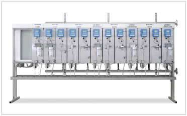
A single-sided rack design offers the advantage of having components (coolers, instruments, and the electrical cabinet) facing the operator. This clearly associates the sampling and analysis equipment with the respective measuring point, which makes the system very simple to operate and maintain. The rack can be installed directly next to a wall, or at any location where access from only one side is available.
A free-standing rack with supports for floor mounting is the standard solution for simple transport and installation. There are also wall-mounted frames, which might be split into different sections. Such a design can be used when the sampling system is installed in a narrow room, to give the operator sufficient space. However, it requires additional efforts for installation (lifting, alignment etc.) and a proper support structure to sustain the weight of the system.
Optionally, the rack can be equipped with a protective roof, lights, leveling elements, or mounting plates for other equipment such as pumps, a drain collector tank, chiller, or chiller bath.
Double-sided sampling rack
By installing components on both sides of the rack (typically, sample conditioning on one side and analyzers on the other), less installation space is required. A double-sided rack is also a suitable solution to accommodate larger systems. It must be ensured that the operator can access both sides of the rack for operation and maintenance.
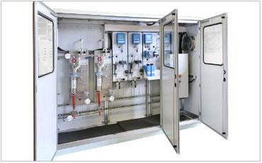
A cabinet can accommodate smaller sampling systems and is mainly used to provide suitable ambient protection when the sampling system is installed outdoors, close to the sampling take-off point. A cabinet can also be used when there is risk of contamination from a very dusty environment or spillage.
Different materials are available for cabinets, including aluminum, painted/galvanized steel, and fiberglass-reinforced plastic. In outdoor installations, sandwich panels are used for better thermal insulation and heaters can be applied for freeze protection. The cabinet is ventilated to evacuate heat from hot samples and instruments. For high ambient temperatures, an AC unit can be installed.
In recent years, with the increase of power plants operating in cycling mode and frequent start stop operations, special automatization features are sometimes requested for the design of sample conditioning and analysis systems. Because some sample conditioning components and analyzers need regular maintenance, complete automation is not possible.
The following chapters contain some recommendations related to these special features which can help prevent highly complex and costly sample conditioning system designs.
Requirements for the complete automation of the sample valves upstream of the sample coolers would make systems very costly and yet offer very limited operational benefits.
The sample shut-off and blow-down valves are designed with a minimum valve cross-section, a special seat, and flow geometry to prevent and minimize clogging caused corrosive particles in the sample and are rated to withstand full process pressure and temperature.
A special pneumatic actuator is necessary if these valves are designed for automatic operation from the main control system. For samples with medium (=300°C) and high (600°C) temperatures, these pneumatically actuated valves need to have an airor water-cooled spindle extension.
Valves like these are not available off-the-shelf and supply and installation costs are quite high.
Typically, sample line flushing is necessary during start-up operations (initial start-up or after extended standstills). More frequent line flushing may be necessary for plants with corrosion issues and a higher content of corrosice particles.
However, frequent sample line flushing does not mean that automatic flushing valves are required. It is a simple operation that lasts only a few minutes and can easily be performed manually.
Sometimes, two sample lines share one sample conditioning panel, for example, where the super-heated steam samples are monitored continuously, and saturated steam samples are monitored regularly for diagnosis or troubleshooting purposes. The chemist or operator decides when to switch the sample line from superheated to saturated steam.
Designing pneumatic valves upstream of the sample cooler for automatic switching significantly increases the cost of the sample conditioning panel and offers no operational benefits, since manual valve switching is a process that lasts only a few minutes.
For fast-start and frequently-started combined cycle plants, the IAPWS states that it is beneficial to keep the key instruments on a continuously refreshing cycle with demineralized water during shutdown or offline periods in order to maintain analyzer operation. The highest priorities are detecting condenser leaks and ensuring steam purity for the turbine admission during startup.
However, it should be noted that automatically flushing with water has some consequences for the critical analyzers: higher consumption of demineralized water is required to keep the analyzer operational while the plant is stopped (an average of 10 l/h per analyzer), the sensitivity of sodium sensors may be reduced if they are continuously flushed with high-purity water, and consumption may be higher for analyzer reagents and other consumables.
Cooling Water: Main Cooling System
In the main cooling water circuit, water quality monitoring is also critical for achieving suitable chemical conditions in the circuit and for automatically controlling of the chemical dosing system. Sample extraction and conditioning are different than other parts of the water steam cycle, but no easier or less important. Since they have different natures and boundary conditions, the sampling systems for the main cooling water and those for the water steam cycle should always be defined.
The sample extraction site must be designed after evaluating the cooling water circuit in each individual power plant to ensure that the sample is always representative of what is happening in the process and that the time lag is minimized as much as possible.
Wherever possible, it is advisable to extract the sample from sites within the circuit where cooling water is continuously flowing. If inline sensors are located in large basins where the water is stagnant, the measurements will not be representative.
Sample are typically extracted from large, open channels or large pipes, running the risk that the sample pressure is insufficient to provide the necessary sample flow and velocity to the analyzers.
It is important to extract the sample on the pressure side of the circuit, to limit the need for a sample pump, cut operating costs, and increase reliability. A sample extraction pump should be used only when there is no other alternative. Sample extraction pumps have a small cross-section because the required sample flow for analyzers is typically below 60 l/h and they are prone to failure (small sump pumps in pits are prone to clogging by particles; suction pumps typically lose suction height due to wear).
Water from the main cooling circuit will have high contents of salts, suspended solids, and organics compound. Therefore, it is important to locate the extraction point in the piping as recommended in Chapter 3.1 to minimize disturbances (suspended solids, gas bubbles, or foam).
It is highly advisable to design a sample line flushing valve at the sampling panel inlet in order to eliminate any suspended solids that have accumulated in the transport line.
If necessary, use fast loop cycling to avoid sedimentation in the sample transport line:  Additionally, depending on the required measurements and analyzers for the main cooling circuit, sample filtration upstream of the analyzers may be also necessary. Some analyzers have an optional automatic cleaning module to reduce maintenance caused by biological activity.
AMI Codes-II chlorine analyzer with the cleaning module option
For measurements such as residual biocide concentration, it is critical that the analyzer is located as close as possible to the process in order to reduce the length of the sample transport line. Therefore, the sampling system for the main cooling water should be designed as a separat subsystem from the main water steam cycle sampling system.
In a power plant’s effluent or wastewater discharge system, it is also mandatory to continuously monitor the water quality parameters to ensure that they comply with local environmental legislation.
The recommendations for locating sample extraction, sample conditioning, and effluent sampling systems are similar to those indicated for the main cooling system in Chapter 8
As per VGB, IAPWS, and EPRI recommendations, the sampling site for condensate is the main condensate downstream of the condensate extraction pumps. Using the main condensate sample for permanent monitoring has the following advantages:
The online analyzers in the main condensate sample indicate condenser leaks early on; the following sampling options are available when attempting to identify the leaking tube sheet:
VGB-S-006-00-2012-0F9-EN recommends that multiple tapping points be installed below the condensate level at various critical locations in the individual condensers and condensate pipes. Grab samples can be extracted at various points and analyzed in the laboratory using a portable membrane pump. Along with comprehensive online monitoring in the main condensate, this setup provides great flexibility and efficient locating of leaks at a reasonable cost.
The affected condenser can be identified quickly from each condenser’s condensate pipe sample. A leak’s probable location within the condenser can be estimated by comparing grab samples taken from different tapping points.
Sometimes, technical specifications from technical consultants and the owners’ engineers will list a condenser hotwell sample and associated online measurements by default. If such requirements are included in an EPC contract, this could cause technical discussions.
A common compromise between the EPC and the operator to provide some form of hotwell condensate monitoring is specific conductivity probes, installed directly in the condenser walls at various locations. The probe closest to the leak should indicate the highest conductivity values.
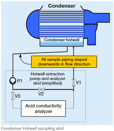
The most expensive and complex sampling setup is a dedicated sampling and instrumentation skid for hotwell condensate. This is technically feasible, but it is complex and quite costly.
Therefore, the need and expected benefit of such a system should be carefully examined and compared with the alternatives listed above. The recommendation is to design such skids only for very large condensers that can be partially isolated on the cooling water side during operation.
Detailed design considerations for this hotwell sampling skid are included in a technical note published by Manuel Sigrist and entitled: “TechNote_Condenser Monitoring_Rev1 3”
Why is it important for an online analyzer to have integrated self-diagnostic capabilities? This way, measured values can be validated, and instruments which provide diagnosis values and alarms can be monitored.
All Swan analytical instruments feature integrated wide-range temperature compensation of their measurements to the reference temperature of
25°C.
Sample temperatures between 5–45°C can be handled by all Swan instruments without measurement bias. Unlike many instruments that require precise thermostatic control of the sample temperature at 25°C, Swan instruments can compensate for the effect of sample temperatures between 5–45°C.
As explained in Chapter 5.3, this limits the need for secondary cooling. Even with a secondary cooling stage, measurements will not be dependent on the chillers’ ability to maintain constant sample temperatures.
For comparison and reference measurements, it is essential to ensure that the handheld and laboratory measuring devices have the same equipment and functionality as the online devices in order to obtain representative and reproducible measurement results. Otherwise, the discrepancies in measurements will lead to increased effort and run the risk that the water and steam chemistry quality status will be assessed incorrectly.
As per VGB-S006-2012, Chapter 5.2 on quality assurance, the quality of continuous online instruments may be ensured by the following technical measures:
1) Proper design of the sampling system and sample conditioning
2) Automatic diagnostic functions being integrated in the instruments, such as:
Typically, modern instruments offer several possibilities for signal exchange, either traditional hardwired analog signals or more modern digital communication (e.g., HART, Bus, etc.)
Power plants today are widely operated in a cycling mode and have fewer operators on duty; therefore, it is essential to have a high thrust in the indicated values in the main control room.
However, this cannot be achieved with analog signals above.
A SWAS with 10 lines, 20 instruments, and a few auxiliaries will typically have around 50–70 signals exchanges with the DCS, which is more than most auxiliaries in a power plant.
When it comes to signal exchange between the SWAS and the DCS, hardwired signal exchange is still required in many power plants.
The alternative is to use digital bus-based communication for signal exchange between the SWAS and the users of SWAS data (the DCS, instrumentation and control (I&C), or chemical department). State-of-the-art instruments offer bus communication options (e.g., Profibus/Modbus).
Modern instruments also offer a digital HART communication option. HART will allow the transmission of more information from the instruments: sample flow, cation resin consumption, reagent levels, error messages, etc.
Swan instruments have optional communication interfaces available for Profibus DP, Modbus RTU, and HART Protocol Revision 7.5.
As described in Chapter 9.2, modern online instruments feature self-diagnostic capabilities to validate the measured values, to monitor instrument status, and to provide diagnostic values and alarms.
If diagnostic information is available, not only in the instrument itself but also remotely, reliable and validated measurements and alarms will be possible in main control system (DCS). This will also increase the trust that operators working in the main control room have in the online analyzers.
In many parts of the world, it is still common practice to specify a SWAS design consisting of what is known as a wet rack and a dry rack.
The wet rack contains the sample conditioning equipment and a grab sampling sink, as well as flow cells and sensors. The dry rack is reserved for transmitter electronics (usually panel-mounted transmitters).
These designs date from a time when transmitters did not have the necessary electrical protection (IP66). State-of-the-art instruments are now designed based on functional arrangements, as recommended by VGB-S006-2012.