
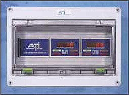
 GasSens Modular Gas Detector, is a flexible component system providing a variety of options to meet individual gas detection and alarm requirements. From chemical and petrochemical plants to food processors, the GasSens modular gas detection system can be applied to the simplest or most complex gas detection application. Economical and low maintenance, this system is your best choice for reliable leak detection.
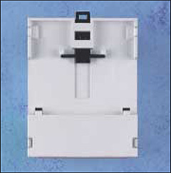
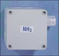
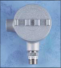
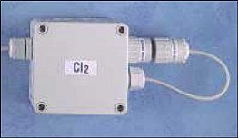
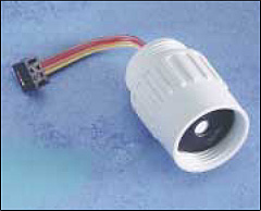
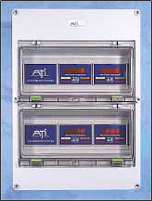
GasSens modular gas detection systems consist of individual modules that can be located where required. Sensor/transmitters, located in the area where gas leakage or buildup might occur, provide the basic measurement for the system. Sensor transmitters are available in either NEMA 4X or explosion-proof versions and can be supplied with ATI’s exclusive Auto-Test automatic sensor testing system, greatly reducing operator testing requirements.
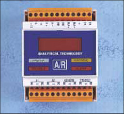
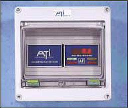
Receiver modules provide the electronic brains for the detection and alarm system. Each compact module includes a digital display of gas concentration, isolated analog output, and 4 relay outputs. Receivers may be located up to 1000 feet from sensor/transmitters for remote indication, or can provide local control functions such as valve shutoff while transmitting a 4-20 mA signal to remote displays or data loggers.
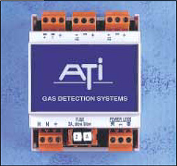
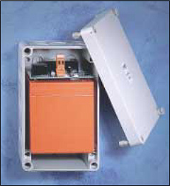
Universal power supply modules provide DC power to receivers. The power supply is housed in a compact module similar to the receiver, and will accept inputs from 85 to 265 volts, AC or DC, without adjustment. The power supply also provides a power failure relay and charging for an optional battery back-up unit.


GasSens Modular Gas Detector, is a flexible component system providing a variety of options to meet individual gas detection and alarm requirements. From chemical and petrochemical plants to food processors, the GasSens modular gas detection system can be applied to the simplest or most complex gas detection application. Economical and low maintenance, this system is your best choice for reliable leak detection.
GasSens modular gas detection systems consist of individual modules that can be located where required. Sensor/transmitters, located in the area where gas leakage or buildup might occur, provide the basic measurement for the system. Sensor transmitters are available in either NEMA 4X or explosion-proof versions and can be supplied with ATI’s exclusive Auto-Test automatic sensor testing system, greatly reducing operator testing requirements.
Receiver modules provide the electronic brains for the detection and alarm system. Each compact module includes a digital display of gas concentration, isolated analog output, and 4 relay outputs. Receivers may be located up to 1000 feet from sensor/transmitters for remote indication, or can provide local control functions such as valve shutoff while transmitting a 4-20 mA signal to remote displays or data loggers.
Universal power supply modules provide DC power to receivers. The power supply is housed in a compact module similar to the receiver, and will accept inputs from 85 to 265 volts, AC or DC, without adjustment. The power supply also provides a power failure relay and charging for an optional battery back-up unit.