Home > Flowmeters > Paddle Wheel Flowmeters > Inline Flowmeter
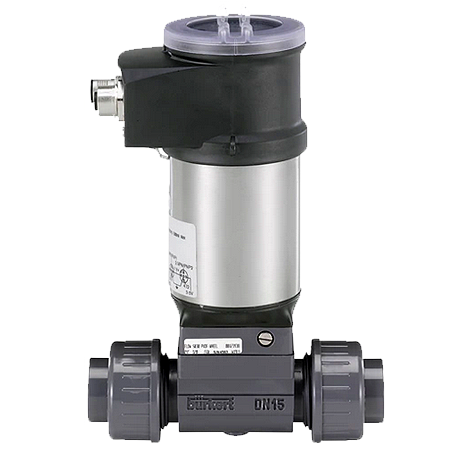
The Burkert type 8036 inline flowmeter is a compact device, specially designed for measuring the flow rate in solid-free liquids, in a variety of applications (water, waste water monitoring, chemical processing, etc.).
Type 8036 is available with:
Type 8036 converts the measured signal, displays different values in different units (if display/configuration module mounted) and computes the output signals, which are provided via one or two M12 fixed connectors. Thanks to 1 or 2 transistor outputs, the flowmeter can be used to switch a solenoid valve, activate an alarm and, thanks to 1 or 2 current outputs, establish one or two control loops.
| Spec | Value |
|---|---|
Non wetted parts |
|
| Housing | Stainless steel 1.4404 (316L), PPS |
| Cover | Polycarbonate (PC), transparent (opaque on request) |
| Display/configuration | module PC Navigation key PBT |
| Seals | EPDM, silicone |
| Screws | Stainless steel 1.4401 (316 (A4)) |
| Fixed connector holder | PPS CF30 |
| Grounding terminal and screw | Stainless steel 1.4301 (304 (A2)) |
| Quarter turn system | PC |
Wetted parts |
|
| Sensor-fitting body, sensor armature |
Brass, stainless steel, PVC, PP or PVDF (depending on S030 version) |
| Seal | FKM or EPDM (depending on S030 version) |
| Axis and bearings | Ceramics (Al2O3) |
| Paddle wheel | PVDF |
| Dimensions | Detailed information can be found in chapter “4. Dimensions” on page 6 |
| Measuring principle | Paddle wheel |
| Compatibility | Any pipe from DN 06…DN 65 which is fitted with Bürkert S030 Inline sensor-fitting. For the selection of the nominal diameter of the Inline flowmeter sensor-fittings, see data sheet Type S030 |
| Pipe diameter | DN 06…DN 65 |
| Measuring range | • Flow rate: 0.5…1200 l/min (0.13…320 gpm) • Flow velocity: 0.3…10 m/s |
Product accessories |
|
| Display/configuration module | Grey dot matrix 128 x 64 with backlighting |
Inline Flowmeter Performance data |
|
| Measurement deviation | Teach-In: ± 1 % of the measured value1.) (at Teach-In flow rate value) Standard K-factor: ± 2.5 % of the measured value1.) |
| Linearity | ± 0.5 % of full scale |
| Repeatability | ± 0.4 % of the measured value |
| 4…20 mA output uncertainty | ± 1 % of range |
| Operating voltage |
Connection to main supply: permanent (through external SELV (Safety Extra Low Voltage) and LPS |
| Power source (not supplied) | Limited power source according to UL/EN 60950-1 standards or limited energy circuit according to UL/EN 61010-1 §9.4 |
| DC reverse polarity protection | Yes |
| Overvoltage protection | Yes |
| Current consumption |
With sensor
|
| Power consumption | Max. 40 W |
| Outputs Transistor |
Protected against overvoltage, polarity reversals and short circuit
|
| Current |
4…20 mA adjustable as sourcing or sinking (in the same mode as transistor):
|
Full details can be found in the 8036 Data Sheet
Type 8036 data sheet | Inline paddle wheel flow sensor with ELEMENT design
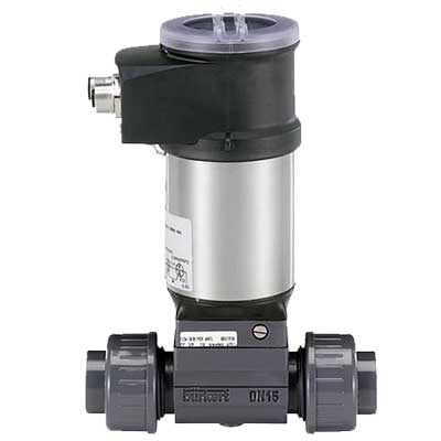

WJF Instrumentation Ltd.
#5 3610 – 29th Street N.E.
Calgary, Alberta
Canada
T1Y 5Z7
Calgary Head Office
Toll-Free: (877)291-5572
Standard: (403)291-5570
Ontario & Maritimes Sales:
(905)809-6918