| Spec |
Value |
| Housing |
PPS |
Non Wetted Parts
|
| Seal |
EPDM |
| Screws |
Stainless steel A4 |
| M12 male fixed plug |
PA |
| Cable gland with 1 m connected cable (on
request) |
PVC (cable) and PA (cable gland) |
Wetted Parts
|
| Fitting |
Brass, stainless steel 1.4404/316L, PVC or PP |
| Seal |
FKM (EPDM option) |
| Axis and bearings |
Ceramics (Al2O3) |
| Paddle wheel, holder |
PVDF |
| Dimensions |
Detailed information can be found in chapter “4. Dimensions” on page 6. |
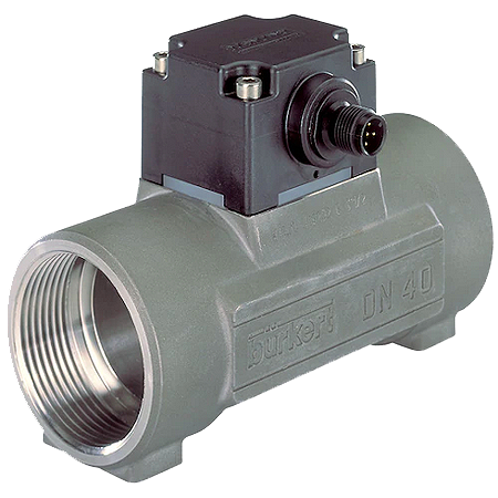
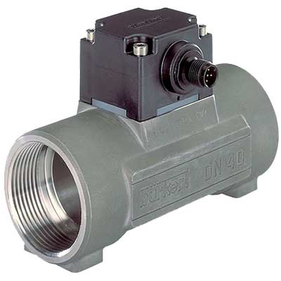
| Measuring element |
Optical – infra-red (or magnetic paddle wheel, on request) |
| Compatibility |
Electronic module (SE12) compatible with Bürkert fitting (S012)
For the selection of the nominal diameter of the S012 fittings, see chapter “6.2. Selection of the nominal diameter” on page 10. |
| Pipe diameter |
DN06…DN50 (DN65 on request) |
| Measuring range |
Flow rate: 0.5…1000 l/min (0.13…265 gpm) – flow velocity: 0.3…10 m/s |
Continuous Flow Measurement Performance Data
|
| Measurement deviation |
- Teach-In1.): ± 1 % of the measured value2.) (at Teach-In flow rate value)
- Standard K-factor: ± 2.5 % of the measured value2.)
|
| Linearity |
± 0.5 % of full scale2.) |
| Repeatability |
± 0.4 % of the measured value2.) |
| 4…20 mA output uncertainty |
± 0.16 mA |
Electrical Data
|
| Operating voltage |
12…36 V DC ± 10 %, filtered and regulated
Connection to main supply: permanent (through external SELV (Safety Extra Low Volt-
age) and LPS (Limited Power Source) power supply) |
| Power Source (not supplied) |
Limited power source according to UL/EN 60950-1 standards or limited energy circuit
according to UL/EN 61010-1 §9.4 |
| DC reverse polarity protection |
Yes |
| Over-voltage protection |
Yes |
| Current consumption |
< 60 mA (at 12 V DC for current version, without load) |
| Outputs |
- Transistor: NPN (default setting) or PNP (configurable on request), open collector
- 700 mA max.
- NPN-output: 0.2…36 V DC (default setting)
- PNP-output: power supply
- Frequency or switching mode
- Operating mode: window or hysteresis threshold
- Protection against over-voltage, polarity reversals and short circuit
- Current: according to version, configurable on request
- 4…20 mA (3 wire), sinking (default setting – configurable as sourcing on request)
- Image of the flow velocity (default setting)
- Loop impedance max.: 1125 Ω at 36 V DC, 650 Ω at 24 V DC, 140 Ω at 12 V DC
|
| Voltage supply cable |
1.5 mm2 max. cross-section |