| Spec |
Value |
Non wetted parts
|
| Housing cover |
PC, glass fibre reinforced |
| Front panel folio |
Polyester |
| Female cable plug/male fixed plug |
PA |
| M12 male fixed plug |
PA or PA and CuZn, nickel-plated |
Wetted parts
|
| Seal |
FKM standard (EPDM included, but not mounted) |
| Sensor-fitting body, sensor armature |
Brass, stainless steel, PVC, PP or PVDF (depending on S030 version) |
| Axis and bearings |
Ceramics (Al2O3) |
| Paddle wheel |
PVDF |
| Dimensions |
Detailed information can be found in chapter “4. Dimensions” on page 7 |
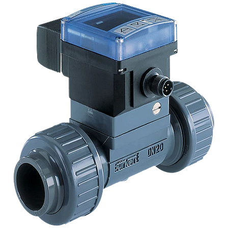
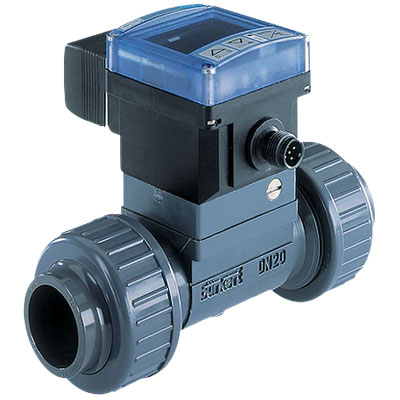
| Measuring principle |
Paddle wheel |
| Compatibility |
Any pipe from DN06…DN65 which are fitted with Bürkert S030 Inline sensor-fitting.
For the selection of the nominal diameter of the Inline sensor-fittings, see data sheet
Type S030 |
| Display |
8-digit LCD with backlighting |
| Pipe diameter |
DN06…DN65 |
| Voltage supply cable |
Max. 100 m length, shielded
- For female cable plug (supplied): external diameter of wire: 6…7 mm, cross section of wires: 0.14…0.5 mm²
- For 5-pins M12 female plug (not supplied): external diameter of wire: 3…6.5 mm, cross section of wires: max. 0.75 mm²
- For 8-pins M12 female plug (not supplied): external diameter of wire: 5.9 mm, cross section of wires: 0.25 mm²
|
Flowmeter Performance data
|
| Measuring range |
0.3…10 m/s |
| Measurement deviation |
Teach-In: ± 1 % of the measured value.) (at Teach-In flow rate value)
Standard K-factor: ± 3 % of the measured value.) |
| Linearity |
± 0.5 % of full scale |
| Repeatability |
± 0.4 % of the measured value |
| Operating mode |
Threshold: window or hysteresis |
Electrical Data
|
| Power supply |
12…36 V DC ± 10 %, filtered and regulated
Connection to main supply: permanent (through external SELV (Safety Extra Low Volt-
age) and LPS (Limited Power Source) power supply) |
| Power source (not supplied) |
Limited power source according to UL/EN 60950-1 standards or limited energy circuit according
to UL/EN 61010-1 §9.4 |
| DC reverse polarity protection |
Yes |
| Current consumption |
≤ 80 mA (no load) |
| Output signal Transistor |
NPN and/or PNP, open collector
- 700 mA max. (500 mA max. per transistor if both transistor outputs are wired)
- 0…300 Hz
- Operation and thresholds can be parametered
- NPN-output: 0.2…36 V DC
- PNP-output: power supply
- Protection against short circuits
|
| Output signal Relay |
Non UL device:
- single relay output: 250 V AC/3 A or 30 V DC/3 A, operation and thresholds can be parametered
- relay output and 4…20 mA current output: 48 V AC/3 A or 30 V DC/3 A, operation and thresholds can be parametered
UL device:
- 30 V AC/42 Vpeak/3 A or 60 V DC/1 A, operation and thresholds can be parametered
|
| Process value |
4…20 mA, galvanic insulation
- Loop impedance max.: 1300 Ω at 36 V DC, 1000 Ω at 30 V DC, 700 Ω at 24 V DC, 450 Ω at 18 V DC, 200 Ω at 12 V DC
- Response time (10…90 %): 3 s with filter 2 (default setting
|