Home > Valves > Hazardous Location Solenoid Valves > 2/2 Way Diaphragm Valve
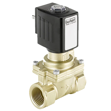
The Burkert type 6281 2/2 Way Diaphragm Valve is a servo-assisted solenoid valve of the S.EV series. A minimum differential pressure is always required for the function of the valve.
Various diaphragm material combinations and methods of operation are available depending on the application.
The standard brass housing satisfies all European drinking water requirements. Dezincification-resistant brass is available for other markets.
The housing offering is rounded out by a stainless steel version. For reduced energy requirement, all coils can be delivered with electronic power reduction.
The valve can be equipped with manual override for easy maintenance and commissioning.
In combination with a plug in accordance with DIN EN 175301 – 803 Form A, the valves satisfy protection class IP65 – in combination with a stainless steel housing NEMA 4X.
| Spec | Value |
|---|---|
Non wetted parts |
|
| Housing cover | PC, glass fibre reinforced |
| Front panel folio | Polyester |
| Female cable plug/male fixed plug | PA |
| M12 male fixed plug | PA or PA and CuZn, nickel-plated |
Wetted parts |
|
| Seal | FKM standard (EPDM included, but not mounted) |
| Sensor-fitting body, sensor armature | Brass, stainless steel, PVC, PP or PVDF (depending on S030 version) |
| Axis and bearings | Ceramics (Al2O3) |
| Paddle wheel | PVDF |
| Dimensions | Detailed information can be found in chapter “4. Dimensions” on page 7 |
| Measuring principle | Paddle wheel |
| Compatibility | Any pipe from DN06…DN65 which are fitted with Bürkert S030 Inline sensor-fitting. For the selection of the nominal diameter of the Inline sensor-fittings, see data sheet Type S030 |
| Display | 8-digit LCD with backlighting |
| Pipe diameter | DN06…DN65 |
| Voltage supply cable |
|
Flowmeter Performance data |
|
| Measuring range | 0.3…10 m/s |
| Measurement deviation | Teach-In: ± 1 % of the measured value.) (at Teach-In flow rate value) Standard K-factor: ± 3 % of the measured value.) |
| Linearity | ± 0.5 % of full scale |
| Repeatability | ± 0.4 % of the measured value |
| Operating mode | Threshold: window or hysteresis |
Electrical Data |
|
| Power supply | 12…36 V DC ± 10 %, filtered and regulated Connection to main supply: permanent (through external SELV (Safety Extra Low Volt- age) and LPS (Limited Power Source) power supply) |
| Power source (not supplied) | Limited power source according to UL/EN 60950-1 standards or limited energy circuit according to UL/EN 61010-1 §9.4 |
| DC reverse polarity protection | Yes |
| Current consumption | ≤ 80 mA (no load) |
| Output signal Transistor | NPN and/or PNP, open collector
|
| Output signal Relay | Non UL device:
|
| Process value | 4…20 mA, galvanic insulation
|
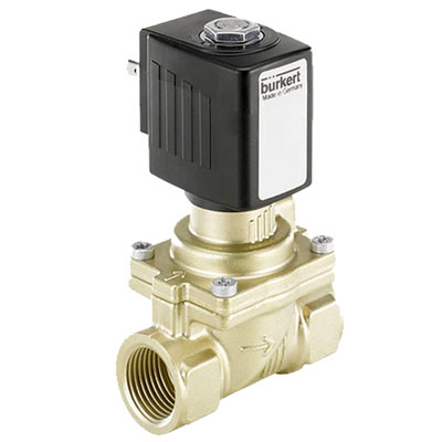
WJF Instrumentation Ltd.
#5 3610 – 29th Street N.E.
Calgary, Alberta
Canada
T1Y 5Z7
Calgary Head Office
Toll-Free: (877)291-5572
Standard: (403)291-5570
Ontario & Maritimes Sales:
(905)809-6918