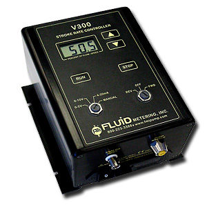
FMI Pump QV Series, Automated Process Control Pump is a variable speed pump with a very high level of accuracy and control. Combined with the V300 Variable Speed Controller. Proportional metering is easy to control with adjustments from 5 to 50 strokes per minute (QVG50) and 90 to 1800 strokes per minute for the QV, QV2 and RHV.
FMI Pump Dispensing Systems feature the patented CeramPump® valveless piston pumping technology. The CeramPump® positive displacement design has one moving part in the fluid path, a sapphire-hard ceramic piston to perform all fluid control functions.
The elimination of valves minimizes downtime or the need for re-calibration and our long term drift-free performance delivers millions of “trouble-free” cycles at 1% precision or better.

On all pumps, flow rates may be altered when operating or at rest. On the “Q” line this is done by turning the Flow Control Knob which moves the flow rate indicator along a fixed 20 unit scale linearly calibrated “10-0-10”. The “10” equals 100% flow rate in that direction, “0” equals zero flow. To improve the fine adjustment of the flow rates on the “Q” line, there is an optional Dial Indicator Kit Q485 which provides for 1000 discrete settings. The “RH” line flow adjustment is accomplished by turning an easy-grip Flow Control Ring graduated in 450 divisions from 0 to 100% flow.
Yes. Pumps will self prime to 15 feet vertical dry, 26 feet wet.
FMI Pump QV Series, Automated Process Control Pump is a variable speed pump with a very high level of accuracy and control. Combined with the V300 Variable Speed Controller. Proportional metering is easy to control with adjustments from 5 to 50 strokes per minute (QVG50) and 90 to 1800 strokes per minute for the QV, QV2 and RHV.
FMI Pump Dispensing Systems feature the patented CeramPump® valveless piston pumping technology. The CeramPump® positive displacement design has one moving part in the fluid path, a sapphire-hard ceramic piston to perform all fluid control functions.
The elimination of valves minimizes downtime or the need for re-calibration and our long term drift-free performance delivers millions of “trouble-free” cycles at 1% precision or better.
On all pumps, flow rates may be altered when operating or at rest. On the “Q” line this is done by turning the Flow Control Knob which moves the flow rate indicator along a fixed 20 unit scale linearly calibrated “10-0-10”. The “10” equals 100% flow rate in that direction, “0” equals zero flow. To improve the fine adjustment of the flow rates on the “Q” line, there is an optional Dial Indicator Kit Q485 which provides for 1000 discrete settings. The “RH” line flow adjustment is accomplished by turning an easy-grip Flow Control Ring graduated in 450 divisions from 0 to 100% flow.
Yes. Pumps will self prime to 15 feet vertical dry, 26 feet wet.