The aim of power cycle chemistry is to prevent corrosion and to avoid deposits in the power cycle. This will reduce downtime and protect expensive components such as boilers, turbines and condensers. All in all, the goal of power plant chemistry is to maintain the designed plant efficiency, the designed life time and to abide by all environmental rules and regulations.
With the exception of precious metals, metallic surfaces are subject to water-induced corrosion when unprotected. In power plants, oxide layers provide the necessary protection. These layers are formed during initial start-up. During operation, the main task is maintaining the integrity of the protective layers.
Metal surfaces and water form an electro-chemical system consisting of an anode, cathode, and electrolyte. The presence of anodes and cathodes is due to small differences between the metallic components’ physical and chemical properties.
Every substance that serves as a conductor for ions (electrically charged particles) is considered an electrolyte. Even high purity water is a conductor because water molecules constantly dissociate into positively charged hydrogen ions (H+ ) and negative hydroxide ions (OH- ). The water’s conductivity is increased by the addition of salts, acids, and alkaline solutions.
The electric conductivity of feedwater, steam, and condensate is clearly the most important parameter to monitor in power cycles.
During start-up, oxidation forms a protective layer on the metallic surfaces. Contaminants such as chlorides and sulfates may damage that layer. Low pH values and high flows (flow-accelerated corrosion) also reduce or eliminate the protection. The result is bare metal that will oxidize again. The cycle starts afresh with the layer’s destruction and subsequent oxidation. It is a matter of days until severe damage appears.
Power cycle chemistry deals with the methods needed to provide and maintain the protective layer.
Analytical instruments are necessary to maintain appropriate levels of purity, pH and oxygen.
The most well-intentioned chemical treatment program may be virtually worthless without appropriate instrumentation. Considering the cost of plant downtime and component replacement, quality assurance is of paramount importance.
Several treatment methods have been recommended and the results are regularly discussed. There is, however, no universal solution. Every power plant is different. The layout of the plant, construction materials, operational pressure, and quality of feedwater and cooling water must be considered before making a choice.
Common treatment methods include:
AVT All-Volatile Treatment:
In addition, there are two treatment methods for boiler waters using a solid alkalization agent:
Full details on the above-mentioned treatments, their selection, and their application can be found in the relevant standards set down by VGB (S-010 and S-006), the IAPWS TGD’s (http://www.iapws.org/techguide.html), and the EPRI documents.
There are nearly as many different power cycles as there are power plants. Basic elements such as feedwater treatment, steam generation and condensation are always present. The search for greater efficiency and lower costs leads to more complex designs.
Online monitoring is essential wherever the quality of water, steam or condensate should not and cannot be replaced by grab samples. This is also clearly stated in all relevant guidelines (VGB, IAPWS, EPRI, etc.). The analytical parameters depend on the design of the power cycle, the construction materials and the chemical treatment.
Designers and chemists have different views with respect to analytical parameters and the number of instruments for online monitoring. The following remarks are limited to the use of Swan instruments.
Conductivity, pH and dissolved oxygen are the most important parameters. Conductivity is measured as specific conductivity and as conductivity after a strongly acidic ion exchanger (acid or cationic conductivity).
In most cases, pH can be calculated from the difference between the two conductivities (see page 20). ORP (redox) analyzers have been added to the traditional online monitoring. All treatments require monitoring of dissolved oxygen. The sampling point is downstream of the feedwater pump and/or at the economizer’s inlet.
Additional oxygen analyzers might be necessary at other locations, such as condensate return from process steam extraction, condensate from district heating or for tight control when OT (= oxygenated treatment) is applied.
Continuous analysis should include pH, specific conductivity and conductivity after cation exchange. Combined cycle power plants can have several heat recovery steam generators and at different pressures. Conductivity and pH are monitored at every step. Sodium analyzers will also help to control carryover. Silica is an important parameter due to its vaporous carryover qualities and tendency to form tenacious deposits on turbine blades.
One reason for monitoring steam is to verify that the steam produced by steam generators meets the manufacturer’s steam quality guidelines. Recommended continuous analyses include cation or preferably degassed cation, sodium and silica. At a high operating pressure, silica and sodium become very important because potential contaminants dissolve faster.
The point of measurement is normally the condensate pump discharge because of the requirement for pressure in the sample line to be greater than atmospheric pressure. Acid conductivity, calculated pH, dissolved oxygen, sodium and sometimes degassed cation conductivity are monitored. Sodium and acid conductivity are monitored for condenser leakage detection. Sodium is much more sensitive than conductivity. It will indicate leaks hours earlier. Acid conductivity will also respond to CO 2, while sodium will indicate other contaminations. Dissolved oxygen mea- surement can provide a valuable indication of the air ingress rate and oxygen entering into the cycle. If a condensate polisher is operated in a bypass, the online values might be used to direct the condensate through the polisher.

Ion exchangers’ performance must be closely monitored. Parameters of choice are specific conductivity, acid conductivity, sodium, and silica. Sodium rapidly alerts the operator to cation breakthrough and hence to the need for resin regeneration. The supplier of the polishers sometimes provides these instruments. It is unfortunate for operation and maintenance if they are of a different make from the ones in the power cycle.
Specific conductivity, sodium, and silica are monitored to prevent contaminants from the water treatment system from being introduced into the power cycle.
Cooling water chemistry is a separate issue. Many different chemicals are used for treatment. The chemicals supplier will indicate the parameters to monitor. As corrosion inhibitors will contaminate many sensors, colorimetric methods are recommended.
Guidelines for the feedwater and steam quality are available from IAPWS or Electric Power Research Institute (EPRI) USA and Vereinigung der Grosskraftwerksbetreiber (VGB) Germany. There are many other country- or organization-specific guidelines in use. Suppliers of components (boilers, turbines, condensers) will include operating parameters in their warranty conditions. They might refer to IAPWS, EPRI or VGB or draw on their own experience.
The online measurement of conductivity after water has passed through a column of strongly acidic cation exchange resin is used to indicate the presence of potentially corrosive ionic contaminants. The technique may be referred to as “cation conductivity” or “acid conductivity” in some documentation. As per IAPWS, the accepted abbreviation is CACE.
This parameter can only be measured online and under no circumstances may it be replaced by grab samples and analysis in the laboratory. Also, this parameter cannot be replaced by a direct conductivity measurement without the cation exchanger what is known as “specific conductivity”.
This is the most important measured value for monitoring the purity in a steam water cycle. Using the strong acidic cation exchanger suppresses the conductivity caused by alkalizing agents (e.g. ammonia). At the same time, contami- nants (e.g. salts) are transformed into their corresponding acids, which show a higher conductivity than the salts. This effect causes the measurement’s sensitivity to increase.
Carbon dioxide, which may enter the steam water cycle either through air in-leakage or which may be produced by thermal disintegration of what are commonly known as organic treatment chemicals (e.g. amines), will increase this value. However, it is not as critical as other impurities, such as chloride or sulfate. Hence, higher values caused by carbon dioxide may be tolerated. If carbon dioxide is expected to be present often or permanently (e.g. when amines are being used), it is highly advisable to use what is typically referred to as a “degassed conductivity measuring device” instead of the standard conductivity after cation exchange device. In this case, the “classic” conductivity downstream strong acidic cation exchanger can be ignored.
The corrosion rate of carbon steel will be reduced at pH values greater than 9. Depending on the design and the materials, as well as the applied treatment program, different limits are applicable. To determine the pH in low-conductivity water samples like feedwater, the most reliable method is to use the calculation method that has proven to be more stable and correct, and that causes less interference.
Oxygen must be measured at all times to ensure that the requirements for the different chemical operating regimes are always securely met.
The presence of sodium, independent of its composition, strongly increases the risk of stress corrosion cracking e.g. on turbine materials. The only way to monitor sodium correctly is by using online instruments.
Silica is partly volatile with the steam, depending on pressure, temperature and alkalinity. At lower-pressure and lower-temperature zones in the turbine, silica transported by the steam will be deposited on the turbine blades. In order to avoid turbine efficiency losses caused by silica layers, it is essential to adhere to the recommended values.
Operation with elevated silica may lead to buildup of silica deposits. Such deposits are not corrosive by themselves, but they impair the flow-passing ability and efficiency of the turbine and can result in axial thrust on the turbine shaft. If they become excessive, they must be removed by means of mechanical cleaning, which requires opening the turbine. The necessary turbine cleaning frequency can be determined by routinely checking the turbine power output and efficiency.
Turbidity measurement is a suitable proxy method for trend monitoring particulate corrosion products in the water steam cycle. The correlation of turbidity with iron/copper depends on several particle properties, like particle size and distribution, which are individual for each plant and can change over time. Consequently, the turbidity measurement cannot replace a proper analysis, and the conversion from turbidity into a concentration will always have a significant error. Nevertheless, turbidity monitoring may be a helpful tool to indicate where the corrosion products are released and how they are distributed, which will at least support further, individual strategies for the plant.
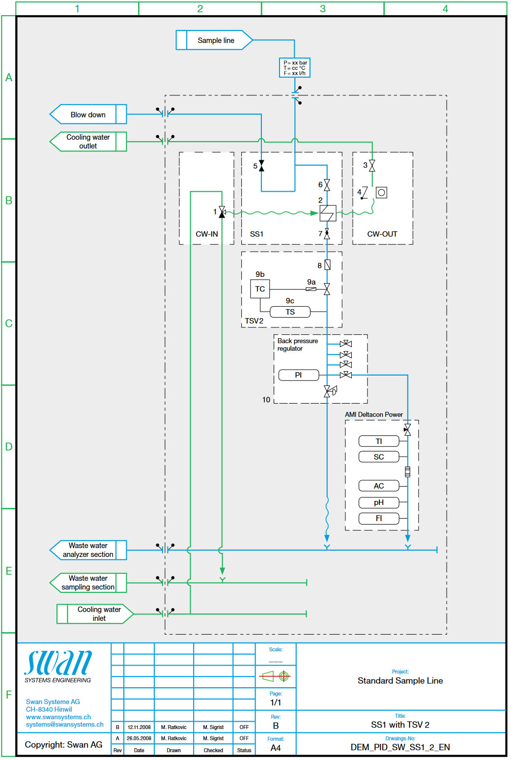
Once the sampling points have been determined and the parameters to be monitored have been chosen, a P&ID (piping and instrumentation diagram) is established.
The first part of the diagram is dedicated to cooling the sample and to reducing the pressure to acceptable levels. This “hot” part is often, also physically, separated from the sample distribution and from the instruments.
A small number of companies have specialized in coolers and valves for these applications. Some will propose secondary coolers to maintain a temperature that is very close to the region of 25°C. This will allow the use of cheaper instruments without temperature compensation. Modern instruments can handle a wide temperature range and will automatically compensate for changes. It is up to the designer to determine which way will ultimately be more economical in the end.
The sample temperature should, however, not exceed 50°C. Higher temperatures might damage sensors or the ion exchangers for the conductivity measurement. It is strongly recommended to install a temperature shut-off valve as a safety device. The P&ID should clearly indicate sample conditions such as flow, pressure and temperature at the point of sample distribution.
Backpressure regulation helps maintain a constant flow to the instruments, which is essential for a correct and precise measurement. A backpressure regulator is indispensable, especially in plants with flexible operation. Every instrument must be equipped with a needle valve and a flow meter to set the sample flow to recommended values. Process instruments may indicate or transmit wrong measured values if the sample flow rate is incorrect and does not remain within the required range.
Traditionally, rotameters are installed before sample distribution. However, a lack of sample flow at an individual instrument cannot be automatically detected with a rotameter before sample distribution. Hence, it is an unreliable design basis. Flow measurements for each online instrument may be integrated in the instrument or installed as a separate unit, and should be connected to a device that can issue an alarm. Modern instruments have integrated flow measurements that are available on signal outputs and/or on alarm relays.
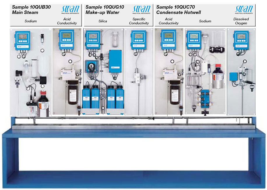
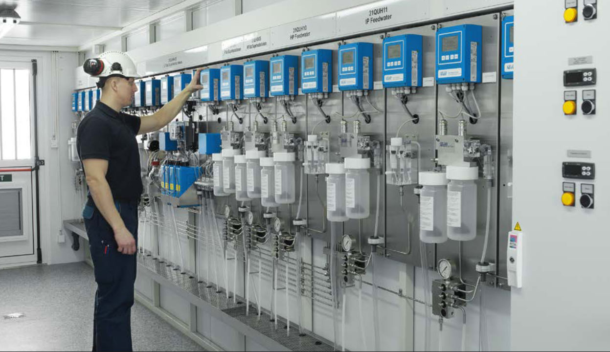
It is common practice to mount the instruments in groups according to their physical properties. All transmitters are mounted on one side, and all the analyzers (silica, sodium, phosphate) on the other. Grab sampling lines are put together over a discharge basin. The wet part with the sensors is often separated from the transmitters. In all these cases, calibration and maintenance work becomes difficult and is often neglected.
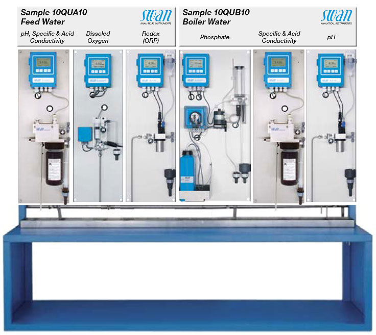
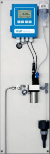
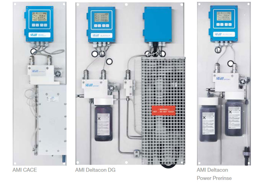
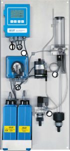
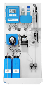
Swan favors systems where all instruments of an identical sample are grouped together so that measured values can be clearly attributed to a sample. Calibration and maintenance are simplified by mounting all the components for an instrument on one panel.
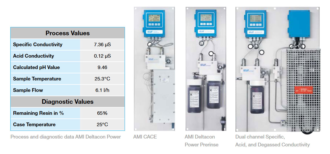
The example shows complete instrument panels arranged by sample line. Whoever stands in front of the panel knows exactly what value belongs to what sample.
Conductivity is by far the most important parameter in power cycle monitoring. It is measured as “specific” (also direct or total) conductivity, as “acid” (also cationic) conductivity after a strongly acidic ion-exchanger, and as degassed cation conductivity.
Conductivity sensors for use in the low microsiemens range consist of two electrodes made of stainless steel or titanium. The cell constant expresses the ratio of the distance between the electrodes to the area of the electrodes. A transmitter provides a constant alternating voltage. The current that flows through the circuit depends only on the resistivity of the liquid between the two electrodes. This resistivity is measured and expressed as its reciprocal value in microsiemens per cm 2 . It provides a measurement for the total presence of conductive matter in the sample.
Conductivity strongly depends on temperature. It is always indicated for a reference temperature of 25°C. The conductivity value must therefore be compensated for the actual sample temperature. Temperature compensation also depends on the nature of the solution. Several temperature curves can be selected at the transmitter. For power cycles, these are: neutral salts, strong acids, strong bases, ammonia, ethanolamine or morhpoline. Linear or nonlinear compensation by coefficient are available for high purity water (polished condensate or makeup). Strong acid temperature compensation is always used when measuring acid conductivity.
Direct conductivity is mostly influenced by the presence of an alkalization chemical such as ammonia. Carbon dioxide will add considerably to the measurement mainly at start-up.
Strong acid cation exchangers have an affinity for cations over hydrogen and will exchange hydrogen for them as water flows through the vessel. This will eliminate the conductivity from the added alkalinization chemical. Other cations are transformed into their respective acids. The sensitivity of the measurement will be increased by a factor of 3 to 3.5. This makes it easier to detect small amounts of contaminating ions. Carbon dioxide will influence the measurement.
Carbon dioxide via air in-leakage or thermal decomposition of organic amines increases the acid conductivity. CO 2 is not as corrosive as contaminants such as chloride and sulfate. Since acid (cation) conductivity is the primary means of detecting contaminants such as chloride and sulfate, it is advantageous to remove as much CO 2 as possible from the sample to determine if the elevated acid (cation) conductivity is due CO 2 or more corrosive ions such as chloride or sulfate.
Conductivity after cation exchange (CACE) is the most important parameter in order to monitor the purity of a water steam cycle. In all water steam cycles, but especially ones with high pH regimes (pH = 9.8), the benefits of the AMI CACE’s are of highest importance.
Conventional cation resin columns are exhausted fast and frequent resin replacement or regeneration is necessary, driving high operating costs. Whereas conventional CACE monitoring relies on costly resin columns to undertake cation exchange, Swan’s AMI CACE online monitor is equipped with a propietory, cost saving electrodeionization module:
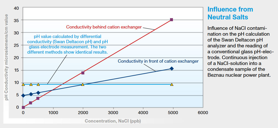
As the strong acid cation exchanger will eliminate the conductivity from the added alkalization chemical, the difference between a measurement upstream and downstream of the exchanger will indicate the amount of this chemical. In many cases, the pH value can be calculated from this difference.
Precision and reproducibility depend on the stability of the electronic transmitter and on the precision of the cell constant.
Remote sample flow monitoring is provided for validating data from online instruments.
Quality instruments do not need calibration. The typical range is around 0.2 µS, and there is no stable calibration solution in this range anyway.
The consumption of the resin in the cation exchanger must be monitored. Resins that change their color when consumed are available. Combining differential conductivity with flow measurement enables automatic monitoring with a remote alarm.
Swan developed the AMI CACE online conductivity monitor with an electrodeionization (EDI) module for automatic and continuous resin regeneration: depleted resin material no longer needs to be exchanged. Swan instruments provide conductivity, temperature, sample flow, resin consumption and self-monitoring features for quality assurance systems.
All treatment methods involve maintaining a certain pH range. However, measuring pH in water with low ionic strength is not an easy job.
 Analytical Method
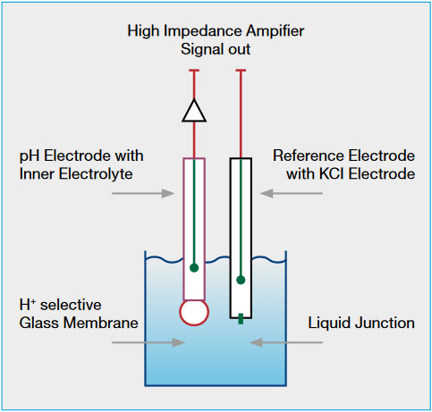
A pH measurement consists of a potential difference (mV) between two electrodes. The reference electrode provides direct contact between the sample and an electrolyte. The measuring electrode is separated by an ion-sensitive membrane from the sample. The potential difference between the two electrodes depends on the number of H+ ions in the sample.
The ion-sensitive electrode and reference electrode can be combined in a single housing. However, in critical applications with low-conductivity water, it is advisable to use two different electrodes.
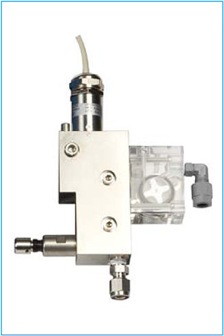
The critical part in a pH measurement is the liquid junction between the sample and the reference electrolyte. Using liquid electrolyte solutions that flow into the sample in very small quantities can eliminate problems.
The flow rate must be stable and constant. There is an influence from the sample flow in high purity water. The sample flow should be between 5 and 10 liters per hour and should be constant at the chosen rate. Atmospheric drain is a must because of possible backpressure at the liquid junction.
Temperature greatly influences the pH measurement. It is always indicated for a reference temperature of 25°C. The pH value must therefore be compensated for the actual sample temperature. Temperature compensation according to the Nernst equation is standard. In critical applications, there are additional linear and nonlinear solution compensations. If pH is calculated from differential conductivity, both conductivity measurements need temperature compensation.
Periodic calibration is required for pH instruments. The ideal pH electrode has an offset of 0 mV at pH 7 and a slope of 59.16 mV/pH unit. Real electrodes differ from this ideal. pH electrodes are therefore calibrated with two buffer solutions of different pH values.
The operator should check that the electrolyte is flowing freely on a regular basis, mainly before a calibration. Remote sample flow monitoring is provided for validating data from online instruments. Process pH, temperature and sample flow are available for quality assurance systems.
 ORP (Redox Potential)
The measurement of the oxidation reduction potential provides insight into the redox condition in the feedwater. Some plants require an ORP measurement for optimum operation.
The ORP measurement consists of a potential difference (mV) between two electrodes, as with the pH. In fact, the reference electrode is identical. The measuring electrode, however, uses a platinum surface where oxidation or reduction takes place. The two electrodes can be combined in a single housing or mounted as two different electrodes.
The critical part is the liquid junction between the sample and the reference electrolyte, as in the pH measurement. Using liquid electrolyte solutions that flow into the sample in very small quantities can eliminate problems. The flow rate must be stable and constant.
There is an influence from sample flow in high purity water. The sample flow should be between 5 and 10 liters per hour and should be constant at the chosen rate. Atmospheric drain is a must because of possible backpressure at the liquid junction. The redox potential is not compensated for temperature.
There is no calibration because the redox potential is a relative value. The sensor performance can be checked on a solution with a known redox potential. The operator should check that the electrolyte is flowing freely on a regular basis, mainly before a calibration process. ORP and sample flow are available for quality assurance systems.
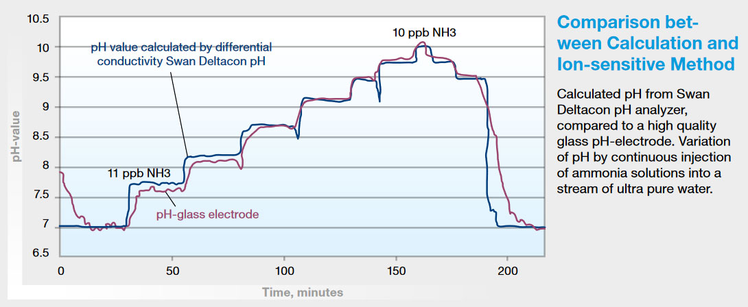
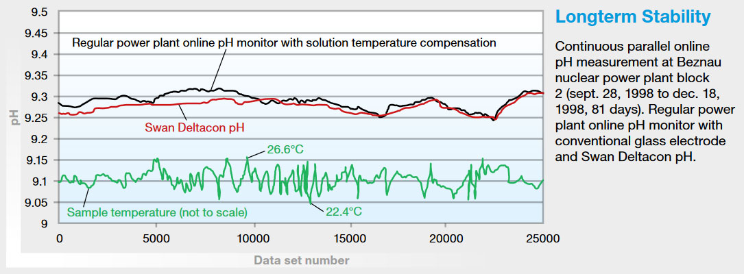
This method for determining the sample pH has been known for many years, and is also recommended by VGB and IAPWS. It is in fact very simple, stable and reliable, and requires low maintenance. It might not have been used widely due to a lack of adequate instruments.
Modern electronics with advanced software can provide a suitable instrument that measures specific and acid (cation) conductivity and calculates the sample pH. It is ideally suitable for combined cycle plants with many sampling points for pH and conductivity.
There are a few restrictions:
Maintenance is identical to the acid conductivity instruments described above. There is no need for calibration.
AMI Deltacon and AMI CACE provide specific conductivity, acid conductivity, calculated pH, temperature, sample flow, resin consumption and other self-monitoring features for quality assurance systems.
 Dissolved Oxygen
Different treatment methods require different levels of dissolved oxygen. With the exception of oxygenated treatments, low levels are required.
The sensor consists of a cathode (gold) and an anode (silver), an electrolyte and a membrane. Oxygen diffuses across the membrane due to partial pressure differences. When a preselected voltage is applied to the electrodes, a current that is proportional to the presence of oxygen in the sample can be measured.
The sample flow has an influence on the result. Hence, it must be kept within certain limits. Alarm contacts should be provided for high/low flow to prevent erroneous measurements. Atmospheric sample drain is required.
The sample temperature has an influence on oxygen’s diffusion rate through the membrane. Temperature also the solubility of oxygen in water. Oxygen sensors have an integrated temperature sensor for compensation in the transmitter.
The zero point is very stable and does not need calibration. A known standard is required for slope calibration. It is readily available in the form of water-saturated air. Exposing the sensor to saturated air just over water, ideally over the flow cell, gives a slope calibration. The transmitter offers a calibration routine that will recognize a stable signal and calibrate automatically.
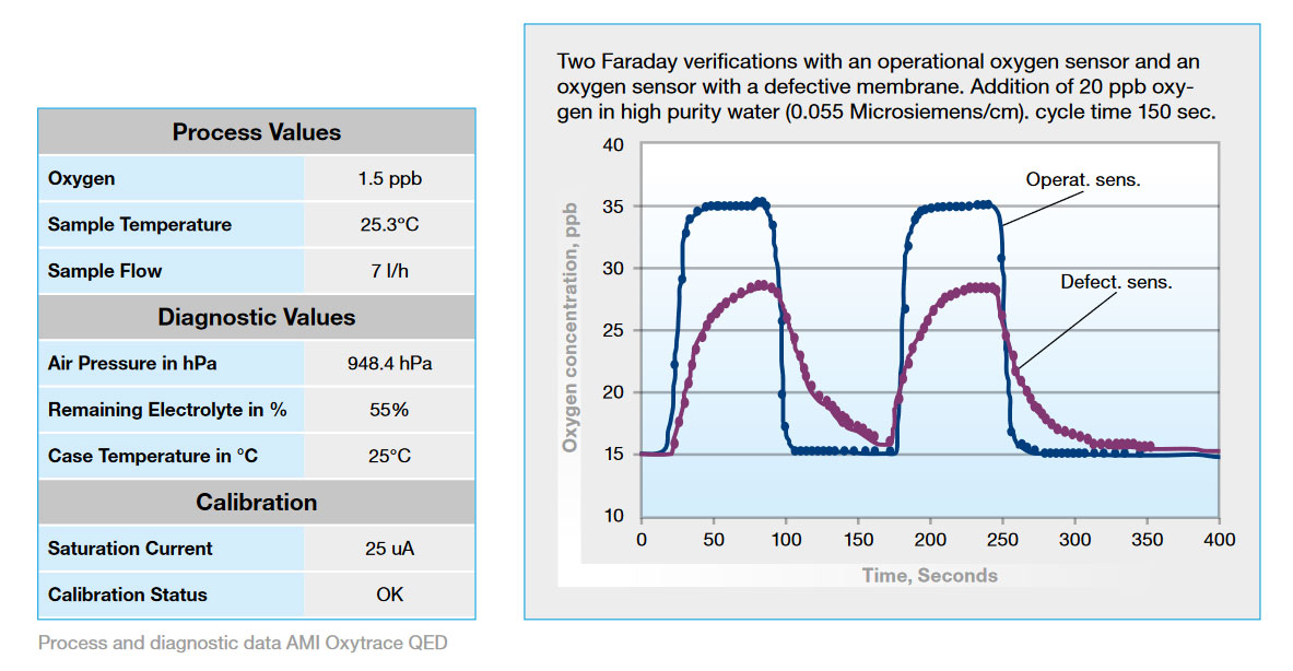
The AMI Oxytrace instruments do not require a great deal of maintenance. It is sufficient to check the sensor in the air once in a while. The transmitter automatically checks electrolyte consumption and membrane integrity.
Special attention should be paid to sampling for dissolved oxygen analyzers. Oxygen is everywhere! It has a fatal tendency of entering the sample through all kinds of connections and materials. Trying to measure multiple streams with the same instrument is asking for trouble.
Remote sample flow monitoring is provided for validating data from online instruments. Dissolved oxygen, temperature and sample flow are available for quality assurance systems.
Low-level measurements are most reliable if the sensor never leaves the sample. Any contact with air will produce downtime because air must be washed out of all parts before a precise reading can be emitted.
Faraday verification is performed by producing a small amount of oxygen through electrolysis upstream of the sensor. As the sensor catches the additional oxygen, it is compared to the generated amount in the transmitter. As long as there is no substantial difference, the instrument works perfectly. Otherwise, an alarm would be issued.
An instrument with Faraday verification will work for many months without requiring maintenance. The result of the verification process is available for quality assurance.
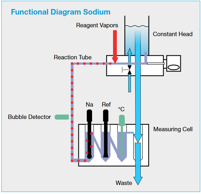
Sodium provides a very fast, selective and very sensitive means of detecting impurities. Sodium also rapidly alerts the operator to cation breakthrough in the demineralized train and, hence, to the need for resin regeneration.
As with pH, there is an ion-sensitive electrode and a reference electrode. The reference is always mounted down- stream of the ion-sensitive port. This prevents cross-contamination from the electrolyte.
Sodium sensors are also sensitive to hydrogen ions. The sample pH must therefore be increased to eliminate these ions. Good results have been achieved by using diisopropylamine. Other alkalinization products might not be strong enough or bear a risk of cross-contamination (NH 3 ). The amount of alkalinization chemical needed depends on sample characteristics and on the lowest detection limit that is required (also see the section entitled “Trace Sodium”).
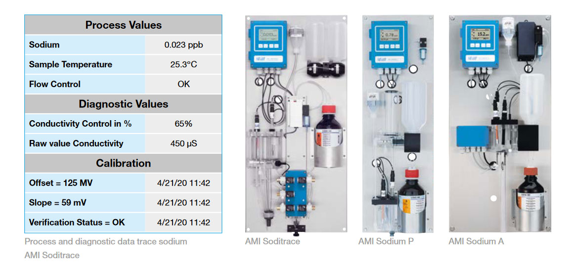
Samples after cation exchangers come with a very low pH and require high volumes of alkalinization chemicals. Active dosing as done with the AMI Sodium A instrument is necessary.
Diisopropylamine is a rather aggressive substance. It might damage instrument components if the sample flow is absent. It is therefore good practice to put a cap on the reagent bottle during downtime.
Temperature compensation is mandatory.
The zero and slope should be calibrated weekly or monthly depending on the application. The sensor should be etched before calibrating to ensure proper response times. It is also necessary to check the flow of the reference electrolyte. Unstable signals very often originate in the reference system.
One of the most common problems in sodium measurements comes from the standard solution. It is extremely important to follow the instructions in the manual carefully. Do not try to use standards lower than 100 ppb. Dilution errors will produce bad calibrations.
AMI Sodium P and AMI Sodium A provide semi-automatic calibration. A valve is manually switched from the sample line to a vessel containing the standard solution. As soon as a stable signal is detected, calibration will be registered automatically. The procedure is normally done with two different standards. The sensor should be etched before calibrating to ensure proper response times.
The AMI Soditrace sodium analyzer has an automatic sensor regeneration process and a more sophisticated auto- matic calibration routine. Multiple known standard additions are carried out automatically at preset intervals. Sodium content, temperature and sample flow are available for quality assurance systems. AMI Soditrace also provides calibration errors.
All possible influence from the hydrogen ion must be eliminated in the trace analysis (< 10 ppt). Reagent addition is therefore controlled with a PID algorithm and the pH is maintained at pH 12.
As the instrument runs out of reagent, false alarms will occur. Monitoring reagent addition will also provide information about system performance and call for maintenance.
As the AMI Soditrace instrument provides fully automated calibration, a standard solution is always available. The standard is diluted down to 10 ppb for automatic verification. As the diluted solution is injected, the sensor will report the increase. If it is within certain limits, the instrument performs well and does not need attention.
Silica is an important parameter for steam and the outlet of makeup plant samples. It is also necessary to detect silica after anion and mixed bed exchangers, as it is the first anion to break through in a demineralizer train.
The colorimetric method is well known and widely used. Reagents are added to the sample and change its color. The intensity of the resulting color is a measure of reactive silica presence.
Sample temperature, pH, and reaction time are the influences to watch. While pH is adjusted to desirable levels by adding reagents, the reaction time is defined by the physical layout of the instrument. The sample temperature influences the reaction time.As the reaction speed increases as the temperature rises, a thermostatically controlled reaction chamber will shorten the reaction time.
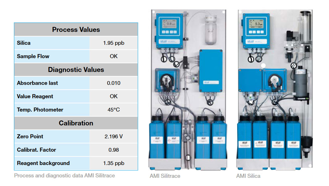
AMI Silitrace uses a thermostatic reaction chamber with a constant temperature of 45°C and only needs 150 s (2.5 min) to complete the reaction. Because the reaction time plays an important role in color development, the pump speed is adjusted constantly. Very high precision is achieved due to the automatic heating and reaction time regulation.
Colorimetric measurements need a base line or zero. Periodically switching off reagent addition and taking a reading without reagent will do this.
Silica-free water is not always available for preparing the reagents. If the reagents’ silica content is known, it can be entered into the instrument to be used to shift the zero point.
Silica analyzers are often used for multiple sample streams. The limiting factor is the required time interval per sample. The switchover time between the sample streams is defined as “Cycle time”. The cycle time must include the “Flush time” and the “Measuring time” of the active sample line.
Samples with fundamentally different silica concentrations should not be combined on a common instrument to avoid carry-over effects and to keep flushing times at a moderate level. It is not advisable to measure steam and boiler water in the same instrument.
Zero should be calibrated frequently, and slope weekly or monthly depending on the application.
In principle, colorimetric methods provide absolute values and do not require slope calibration. It does, however, make sense to periodically verify the instrument’s functions. On the AMI Silitrace instrument, the calibration, verification or zero measurement can be performed automatically according to a programmed time schedule or started manually. It is highly advisable to proceed to verification after changing reagents. This will help to detect errors in reagent preparation.
AMI Silica has a “Verification Kit” available to verify the photometer. An optical window with a precisely determined absorbance value is placed into the photometer’s light beam. The actual measured absorbance will be compared to the reference value indicated on each kit.
Maintenance problems affecting tubing and pumps in analyzers are well known. Swan has developed a unique reagent dosing system with one pump: the tubes of the peristaltic pump are exposed to minimal wear. It is therefore advisable to replace the pump tubes every six months.
Reports to quality assurance systems include the silica process value and diagnostic information such as sample flow and reagent availability. The zero point is also reported. This value will indicate photometer contamination when it is too high.
It is advisable to install online monitors when phosphate treatment is used for boiler water to enable unam- biguous dosing control in boilers that are subject to hide-out.
The measurement of orthophosphate is based in the vanadomolybdo-phosphoric acid method. Silica does not interfere with this measurement method.
Boiler water
AMI Phosphate HL has a “Verification Kit” available to verify the photometer. An optical window with a precisely determined absorbance value is placed into the photometer’s light beam. The actual measured absorbance will be compared to the reference value indicated on each kit. Reports to quality assurance systems include the PO4 process value and diagnostic information such as sample and reagent availability. The zero point is also reported. This value will indicate photometer contamination when it is too high.
 Turbidity
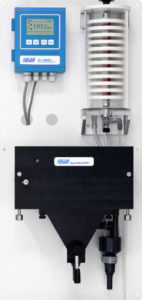
Turbidity measurement is a suitable proxy method for trend monitoring particulate corrosion products in the water steam cycle: especially during power plant start-up and transient loads, and for plants operated flexibly and cycling.
Analytical Method
Turbidity measurement is based in the nephelometric system. A water sample containing undissolved particles scatter the radiation unequally in all directions. To obtain the sample’s turbidity value, the diffuse radiation is determined at an angle of 90°. The light beam of the LED (light-emitting diode) impinges the water surface and is refracted. At an angle of 90°, the detector measures the incoming, scattered light. A beam trap prevents light reflections thus avoids measurement error.
For detecting particles in the water steam cycle (colored oxides particles), the analyzer should be equipped with a LED emitting light with a wavelength of 860 nm (near-infrared LED) according to ISO 7027. The AMI Turbiwell Power is based on ISO 7027 and uses a contactless turbidimeter to prevent optical surface fouling. Correlation of turbidity with iron/copper concentration depends on several particle properties, like particle size and distribution, which are individual for each plant and can change over time. Consequently, the turbidity measurement cannot replace a proper analysis, and the conversion from turbidity into a concentration will always have a significant error. Nevertheless, turbidity monitoring is a helpful tool to indicate where the corrosion products are released and how they are distributed, as provided by real-time measurements.
The AMI Turbiwell Power is calibrated at the factory using formazine and the curve is permanently stored in the transmitter. In addition, the LED’s emission intensity is monitored by an external photodiode. This automatically compensates for an age- related loss of intensity. Recalibration of the instrument at field is therefore not necessary.
The solid verification kits (low and high turbidity), consisting of a glass prism with a defined turbidity value, can be used for verification.
The AMI Turbiwell Power uses a contactless turbidimeter to prevent optical sur- face fouling, reducing cleaning requirements. The drain valve is used for manual or automatic periodic chamber cleaning.
Reports to quality assurance systems include the turbidity process value and diagnostic information such as the sample flow.
 Free Residual Chlorine
Cooling water treatment chemicals are sometimes of a complex and not always known composition. In all cases where the disinfectant cannot be identified as chlorine gas or sodium hypochlorite (NaOCI), it is safer to use a colorimetric analyzer. The same applies when corrosion inhibitors are added and/or at a cooling water pH above 8.5.
The sample flows from an overflow vessel to a mixing chamber into the reaction tube and through the photometer. Reagent is added to the mixing chamber in a preprogrammed sequence. Oxidizing substances in the sample will produce a red color. Its intensity is a measure of the sum of all oxidizing species present.
The user will select the parameter (free chlorine, hypochlorous acid, chlorine dioxide, ozone) in which to express the result on the keyboard.
The water quality and small alterations to the optical system will influence the results. These influences are screened out by taking a zero just before adding reagents.
The reagents contain a buffer solution to adjust the pH to the optimum level. The analysis does not, therefore, depend on the sample pH. Other disinfectants such as chloramines and ozone require slightly different reagents.
Zero calibration is performed automatically before adding a reagent. In principle, colorimetric methods provide absolute values and do not require slope calibration. It does, however, make sense to verify the instrument’s functions after the reagents have been replaced. A comparative measurement with a portable photometer (Chematest or equivalent) will detect errors.
AMI Codes has a “Verification Kit” available to verify the photometer. An optical window with a precisely determined absorbance value is placed into the photometer’s light beam. The actual measured absorbance will be compared to the reference value indicated on each kit. Reports to quality assurance systems include the process value (disinfectant) and diagnostic information such as sample flow and reagent availability. The zero point is also reported. This value will indicate photometer contamination when it is too high.
Sampling and instrumentation must integrate as a subsystem into the plant’s complex control and instrument design. Exact documentation is required to prevent problems during installation and commissioning. The suppliers of instrument racks normally deliver completely wired panels with terminals in a common cabinet.
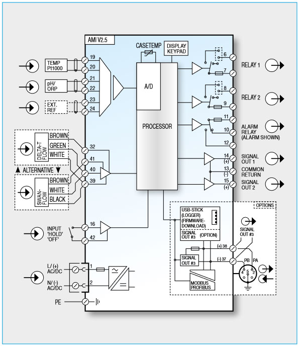
Transmitters are available for different supply voltages (100–240 V AC, 50/60 Hz, or 10–36 V DC). Analyzers that have higher power consumption, however, cannot operate on 24 V DC. It is therefore common practice to use the standard available voltage. Fuses are already present in the instruments, but there must be a way to cut off individual instruments from the power supply for maintenance purposes.
Analog signals (4–20 mA) are still widely used. All the signals are put together on a terminal strip. These signals do not provide information about error conditions such as a lack of sample flow. Every instrument has one potential-free contact for summary alarm indication for programmable alarm values and instrument faults (i.e. no sample flow, no reagent, etc.). It is possible to control dosing pumps directly with a signal from an instrument. Most instruments (pH, chlorine) have built-in PID controllers.
 Ground Loops
All instruments are connected to earth for safety. Most have, however, another grounding through the sensor in the sample water. To prevent problems, the sensor interface must be electrically isolated from the rest of the instrument.
Signal outputs should also be isolated. The sampling system is only a module with a bigger design and you never know what will be on the other end.
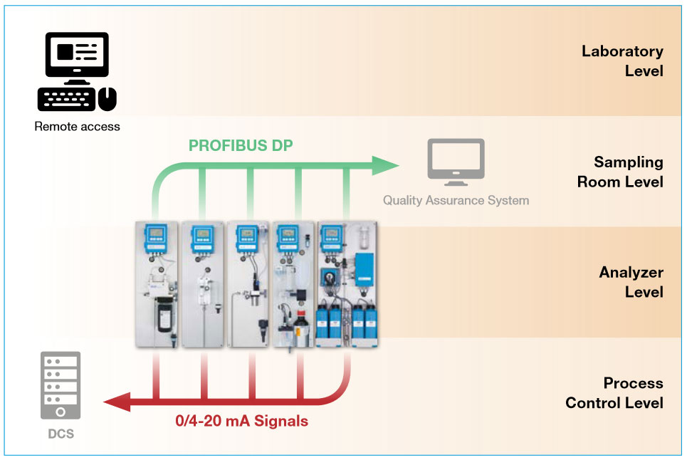
A fieldbus is commonly used in power plants. Swan instruments all offer PROFIBUS DP and MODBUS RTU. Fieldbus connections are easy to install. The bus cable leads from one instrument to the other. If an instrument fails, it drops out of the line, but the other communication links remain intact.
The amount of information that can be transmitted through a fieldbus depends only on parameter availability in the instrument. Remote and automated quality assurance requires not only process values, but also information about sample flow, reagent availability, and sensor integrity.
Swan has installed systems where the analog signal remains available for the power plant’s DCS system while the fieldbus links all instruments to a PLC + HMI in a remote laboratory for automated quality assurance.
Swan also has the HART communication protocol that can transmit the process values as well as the sample flow, reagent availability, and sensor integrity.
Analog signals provide process values without any qualification. The sodium value of condensate leakage detection might seem all right. If there is no sample, however, nobody will notice without going to physically inspect the instrument. Some operators will check the sample flow on critical instruments several times per day. Instruments used to measure key parameters must transmit either a dedicated summary alarm or a status of each measured value during digital bus communication to the DCS.
Every Swan online instrument is equipped with integrated, autonomous quality assurance functions to survey the plausibility of each measurement, Fieldbus and HART systems can transmit quality information provided it is available from the instrument’s memory.
Process, diagnostic and quality assurance information can be collected on a PLC and displayed on an HMI screen. The user can have different operation levels:
Process values are displayed on the DCS, and local PLC + HMI if available at the plant. Process data is stored in the memory and can be displayed as a graph. A process value should emit an alarm if the instrument fails or there is no sample, to validate the measured value.
Diagnostic information is available to evaluate the instrument’s performance. Diagnostic data screens are different for each parameter, as the required information is not identical.